Recently [Big Clive], everyone’s favorite purveyor of anything electronic that’s dodgy, cheap, cheerful, decidedly crispy or any combination thereof, got sent a very dead external power supply unit. Being clearly a third-party PSU with poorly written and many (likely not truthful) safety approval markings on its label, this PSU had the dubious honor of having destroyed a Microsoft Surface computer as well as the monitor that was connected at the time.
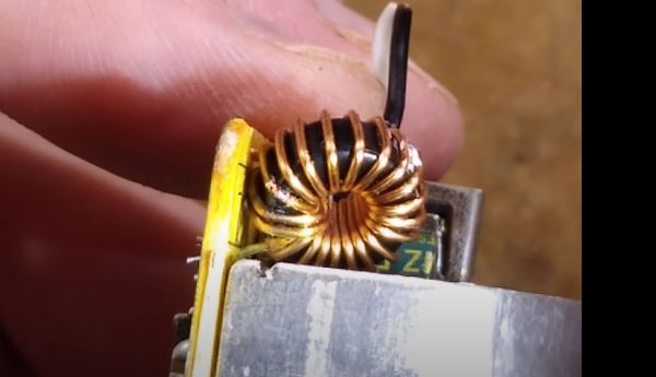
In [Clive]’s video (also embedded after the break) the black and very crispy board is examined, showing a wealth of vaporized traces and plenty of soot. What’s however most fascinating is the failure mode: instead of something obvious like e.g. the main transformer between the primary and secondary side failing, here it would seem that an inductor (see heading image) on the secondary side had its insulation rubbed off and shorted on a nearby heatsink. A heatsink that just happened to be also electrically connected on the primary (mains-level) side.
Judging by the former owner’s report and aftermath, this led to a very sudden and violent demise of the PSU, with mains power very likely making its way into the unsuspecting Surface system and connected monitor. The number of ‘very nope’ design decisions made in this PSU are astounding, and a lesson for both aspiring EEs and anyone considering getting a ‘cheap’ third-party replacement PSU.
(Thanks to [Helge] for the tip)
Continue reading “The Little Replacement PSU That Could: Kill A Microsoft Surface And Monitor”