3D Printed Absolute Encoder Is Absolutely Wonderful

When you need to record the angle of something rotating, whether it’s a knob or a joint in a robotic arm, absolute rotary encoders are almost always the way to go. They’re cheap, they’re readily available, and it turns out you can make a pretty fantastic one out of a magnetic sensor, a zip tie, and a skateboard bearing.

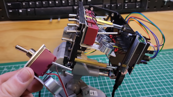
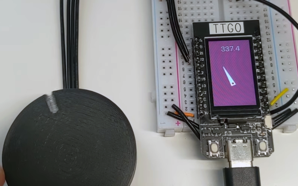
When [Scott Bezek] got his hands on a AS5600 magnet sensor breakout board, that’s just what he did. The sensor itself is an IC situated in the middle of the board, which in Scott’s design sits on a 3D-printed carrier. A bearing mount sits atop it, which holds — you guessed it — a bearing. Specifically a standard 608 skateboard bearing, which is snapped into the mount and held securely by a zip tie cinched around the mount’s tabs. The final part is a 3D-printed knob with a tiny magnet embedded within, perpendicular to the axis of rotation. The knob slides into the bearing and the AS5600 reads the orientation of the magnet.

Of course, if you just wanted a rotary knob you could have just purchased an encoder and been done with it, but this method has its advantages. Maybe you can’t fit a commercially-available encoder in your design. Maybe you need the super-smooth rotation provided by the bearing. Or maybe you’re actually building that robotic arm — custom magnetic encoders like this one are extremely common in actuator design, and while the more industrial versions (usually) have fewer zip ties, [Scott]’s design would fit right in.

Continue reading “3D Printed Absolute Encoder Is Absolutely Wonderful”

The Raspberry Pi CM4 Begets A Form Factor

It has become the norm for single-board computers to emerge bearing more than a passing resemblance to the Raspberry Pi, as the board from Cambridge sets the hardware standard for its many competitors. This trend has taken an interesting new turn, as a new board has emerged that doesn’t sport the familiar 40-pin connector of the Pi Model B, but the more compact from factor of the Compute Module 4. The Radxa CM3 sports a Rockchip RK3566 quad core Cortex-A55 running at 2.0 GHz, and is to be made available in a variety of memory specifications topping out at 8 GB. It is hardware compatible with the Pi CM4, and should be usable with carrier boards made for that module.

We’ve looked at the CM4 as the exciting face of the Raspberry Pi because the traditional boards have largely settled into the same-but-faster progression of models since the original B+ in 2014. The compute module offers an accessible way to spin your own take on Raspberry Pi hardware, and it seems that this new board will only serve to broaden those opportunities. Radxa are the company behind the Rock Pi series of more conventional Raspberry Pi clones, so there seems every chance that it will reach the market as promised.

Will it make sense to buy one of these as opposed to the Pi CM4? On paper it may have some hardware features to tempt developers, but like all Pi clones it will have to bridge the software gap to be a real contender. The Raspberry Pi has never been the fastest board on the market at any given time, but it has gained its position because it comes with a well-supported and properly updated operating system. For this board and others like it that will be a tough standard to match.

Curious as to what the first Raspberry Pi form factor clone was? We think it’s the SolidRun Carrier-one from 2013.

Via CNX Software.

Cheap DIY Mic Sounds (And Looks) Damn Good

As any musician, podcaster, or youtuber will be quick to tell you, there’s no substitute for a good microphone. They’ll also be quick to tell you all about their favorite microphone, why it’s better than all the others, and how much it cost (oh, and how round it sounds, whatever that means). But what if you could build your own that sounds as good, if not better, and do it for only $30?

That’s what [Matt] from DIY Perks set out to discover when he built his DIY USB-C Microphone. He was able to source the same microphone capsule that can be found in his high-end, $600 CAD E100S, and built a simple pre-amplifier that bumps its quiet output up to line-level. He even connected it to the mic module with some custom cable made from two tiny enameled wires that won’t transmit bumps and vibrations, wrapped inside desoldering braiding which acts as a shield. He fed the output from the pre-amp into a cheap USB audio interface and voilà! — top-notch sound for next to nothing. Make sure you check out the video below to hear a comparison between the mic and its professional counterparts.

Of course, sounding good isn’t quite enough. [Matt] wasn’t satisfied until the piece looked the part as well, which is why he encased the mic module in custom-bent brass mesh shielding and tubing (which also helps to reduce electrical interference). The brass cage sits suspended via rubber o-rings on a beautiful bent brass mount, which sits atop an articulated brass arm of [Matt]’s own design. Finally, the arm is mounted to a wood and brass enclosure that also serves to house the electronics.

And, in true open-source fashion, the video description is full of links to parts, schematics, and templates in case you want to build one of these beauties for yourself. Between this fantastic build and this other, super-overkill scratch-built USB microphone we featured earlier in the year, there has never been a better time to make yourself a mic you won’t have to trade your car for.

Thanks to [RichV] and [BaldPower] for the tip!

Continue reading “Cheap DIY Mic Sounds (And Looks) Damn Good”

Space Shuttle Model In A Hypersonic Wind Tunnel

Mach 20 In A Wind Tunnel: Yes, It’s Rocket Science

Hypersonic speeds are defined by those exceeding Mach 5, and lately there’s been a lot of buzz about unmanned hypersonic vehicles making test flights. Vehicles returning from orbital flight also travel at hypersonic speeds as they do their best to transition back to the terrestrial realm. Before anything leaves ground though, these machines are tested in wind tunnels. [Scott Manley]’s video “How Hypersonic Wind Tunnels Recreate Mach 20” (embedded below) does a wonderful job of explaining the engineering behind wind tunnels for testing hypersonic vehicles.

While the earliest wind tunnels such as that used by the Wright Brothers were powered by simple fans, it is not possible for any propeller to surpass subsonic speeds. This is evidenced by there not being any propeller driven aircraft that can exceed Mach 1. Since an aircraft can’t reach those speeds with a propeller, it follows that a wind tunnel cannot be driven by propellers, fans, or any such device, and exceed Mach 1 wind speed, either. So it begs the question: Just how do they do it?

You might think that the answer lays in Bernoulli’s law – but it does not. You might think it involves compressing the air into smaller and smaller tubes and pipes. It doesn’t. As [Scott Manley] so expertly explains in the video below the break, it has quite a lot in common with actual rocket science.

You may be interested to know that we’ve covered some DIY wind tunnel builds as well as a small desktop wind tunnel in the past. While not hypersonic, they’re exactly what you’d want to have if you’re an aerospace hacker of any kind.

Thanks [Zane Atkins] for the tip!

Continue reading “Mach 20 In A Wind Tunnel: Yes, It’s Rocket Science”

Hardware Project Becomes Successful Product For Solo Developer

[Michael Lynch] has been a solo developer for over three years now, and has been carefully cataloguing his attempts at generating revenue for himself ever since making the jump to being self-employed. Success is not just hard work; it is partly knowing when the pull the plug on an idea, and [Micheal] has been very open about his adventures in this area. He shares the good news about a DIY project of his that ended up becoming a successful product, complete with dollar amounts and frank observations.

About a year ago, we covered a project he shared called TinyPilot, which is an effective KVM-over-IP device, accessible over the web, that could be built with about $100 worth of parts. [Micheal] found it to be a fun and useful project, and decided to see if he could sell kits. However, he admits he didn’t have high expectations, and his thoughts are probably pretty familiar to most hardware types:

I questioned whether there was a market for this. Why would anyone buy this device from me? It was just a collection of widely available hardware components.

Well, it turns out that he was onto something, and the demand for his device became immediately clear. He’s since given TinyPilot more features, an attractive case, and even provides a support plan for commercial customers. This is an excellent reminder that sometimes, what is being sold isn’t the collection of parts itself. Sometimes, what’s being sold is a solution to a problem people have, and those people are time-poor and willing to pay for something that just works.

It’s great to see [Michael] find some success as a solo developer, but his yearly wrap-up covers much more than just the success of TinyPilot as a product, so be sure to check it out if you’re at all interested in the journey of working for yourself.

A Builders Guide For The Perfect Solid-State Tesla Coil

[Zach Armstrong] presents for your viewing pleasure a simple guide to building a solid-state Tesla coil. The design is based around a self-resonant setup using the UCC2742x gate driver IC, which is used in a transformer-coupled full-wave configuration for delivering maximum power from the line input. The self-resonant bit is implemented by using a small antenna nearby the coil to pick up the EM field, and by suitably clamping and squaring it up, it is fed back into the gate driver to close the feedback loop. Such a setup within reason allows the circuit to oscillate with a wide range of Tesla coil designs, and track any small changes, minimizing the need for fiddly manual tuning that is the usual path you follow building these things.

Since the primary is driven with IGBTs, bigger is better. If the coil is too small, the resonant frequency would surpass the recommended 400 kHz, which could damage the IGBTs since they can’t switch much faster with the relatively large currents needed. An important part of designing Tesla coil driver circuits is matching the primary coil to the driver. You could do worse than checkout JavaTC to help with the calculations, as this is an area of the design where mistakes often result in destructive failure. The secondary coil design is simpler, where a little experimentation is needed to get the appropriate degree of coil coupling. Too much coupling is unhelpful, as you’ll just get breakdown between the two sides. Too little coupling and efficiency is compromised. This is why you often see a Tesla coil with a sizeable gap between the primary and secondary coils. There is a science to this magic!

Pretty Lithium Carbonate plasma

A 555 timer wired to produce adjustable pulses feeds into the driver enable to allow easily changing the discharge properties. This enables it to produce discharges that look a bit like a Van De Graaff discharge at one extreme, and produce some lovely plasma ‘fire’ at the other.

We’ve covered Tesla coils from many angles over the years, recently this plasma tweeter made sweet sounds, and somehow we missed an insanely dangerous Tesla build by [StyroPyro] just checkout that rotary spark gap – from a distance.

Continue reading “A Builders Guide For The Perfect Solid-State Tesla Coil”

magnetic toggle swtches

Modified Toggle Switches Grace Hyper-Detailed Cockpit Simulator Panels

In the world of the cockpit simulator hobby, no detail is too small to obsess over. Getting the look and feel of each and every cockpit control just right is important, and often means shelling out for cockpit-accurate parts. But not always, as these DIY magnetically captured toggle switches show.

Chances are good you’ve seen [The Warthog Project]’s fantastically detailed A-10 Thunderbolt II cockpit simulator before; we’ve featured it recently, and videos from the ongoing build pop up regularly in our feeds. The sim addresses the tiniest of details, including the use of special toggle switches that lock into place automatically using electromagnets. They’re commercially available, but only for those with very deep pockets — depending on the supplier, up to several thousand dollars per unit!

The homebrew substitute is mercifully cheap and easy to build, though — a momentary DPST toggle switch is partially gutted, with a length of nail substituted for one of its poles. The nail sticks out of the back of the switch, where a bracket holds a small electromagnet. When energized, the electromagnet holds the nail firmly when the switch is toggled on; the simulated pilot can still manually toggle the switch off, or it can be released automatically by de-energizing the coil. Each switch cost less than $20 to make, including the MOSFETs needed to drive the coils and the Arduino to provide the logic. The panels they adorn look fantastic, and the switches add a level of functional detail that’s just right for the whole build.

Continue reading “Modified Toggle Switches Grace Hyper-Detailed Cockpit Simulator Panels”