Aviation instruments are highly interesting pieces of engineering, and it is quite satisfying to watch the often over-engineered mechanisms behind them. If you are into that sort of thing it is worthwhile to check out [Erik Baigar]’s video where he explains the working principle of the attitude indicator from a Tornado jet.

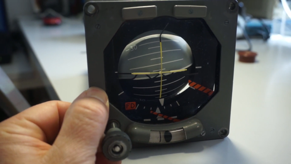
The attitude indicator or artificial horizon of an airplane is one of the most important instruments, especially during poor sight. The ADI42-124 used in the Tornado jet is completely standalone and only needs a DC power supply which is why [Erik Baigar] can show it off while standing on his balcony. At the heart of this instrument is a gyroscope which consists of a spinning disc attached to a gimbal mount. Due to the conservation of angular momentum, the spin axis will always keep its orientation when the instrument is rotated. However, mechanical gyroscopes tend to drift over time and therefore include a mechanism to keep the spin axis upright with respect to the direction of gravity. The ADI42-124 uses an entirely mechanical mechanism for this based on free swiveling weights. Forget everything we said earlier about overengineering as [Erik Baigar] also uncovers a fatal design flaw which leads to the instrument’s self-destruction as shown in the picture here. Unfortunately, this will render most of the units you can buy on eBay useless.
Be sure to check out [Erik Baigar]’s webpage which is nerd paradise for vintage computer and avionics fans or watch another gyroscope teardown.
Video after the break.
Continue reading “Fighter Jet’s Gyro Stays Upright Before It Self-Destructs”