Us: “I’ll take Retro style displays we absolutely have to have for $200, Alex.”
Trebek: “This nixie tube is unlike any conventional tube you’ve seen before, handbuilt and NOT numbers or letters.”
Us: “What is FriendlyWire’s new logo tube?”
Trebek: “Heck yeah.”
Nixie tubes are the vacuum technology that manages to do far less than a graphic LCD while looking about a million times cooler. Generally speaking, these tubes are no longer manufactured, and the old stock you can get your hands on usually contain a set of filaments shaped like numbers. But @FriendlyWire’s tweet of this Nixie tube by [Dalibor Farny] breaks both of those rules. This handmade tube isn’t just a numerical display or a colon display (the punctuation mark, get your head out of the gutter). It’s a custom logo, and it’s beautiful.
Hardware is hard, manufacturing only happens in China, accurate pricing is a dark art. Facts which are Known To Be True. And all things which can be hard to conquer as an independent hardware company, especially if you want to subvert the tropes. You may have heard of [Spencer Wright] via his superb mailing list The Prepared, but he has also been selling an unusual FM radio as Centerline Labs for a few years. Two years ago they relaunched their product, and last year the price was bumped up by a third. Why? Well, the answer involves more than just a hand wave about tariffs.
The Public Radio is a single-station FM radio in a mason jar. It’s a seemingly simple single purpose hardware product. No big mechanical assemblies, no complex packaging, not even any tangential accessories to include. In some sense it’s an archetypically atomic hardware product. So what changed? A normal product is manufactured in bulk, tested and packaged, then stored in a warehouse ready to ship. But TPR is factory programmed to a specific radio station, so unless Centerline wanted one SKU for each possible radio station (there are 300) this doesn’t work. The solution was domestic (US) just in time manufacturing. When a customer hits the buy button, a unit is programmed, tested, packed, and shipped.
As with any business, there is a lot more to things than that! The post gives the reader a fascinating look at all the math related to Centerline Labs’ pricing and expenses; in other words, what makes the business tick (or not) including discussion of the pricing tradeoffs between manufacturing different components in Asia. I won’t spoil the logical path that led to the pricing change, go check out the post for more detail on every part.
We love hearing about the cottage hardware world. Got any stories? Drop them in the comments!
If you’ve been reading Hackaday for awhile, there’s an excellent chance you’ve seen a project or two powered by the Smoothieboard. The open source controller took Kickstarter by storm in 2013, promising to be the last word in CNC thanks to its powerful 32-bit ARM processor. Since then we’ve seen it put to use in not only the obvious applications like 3D printers and laser cutters, but also for robotic arms and pick-and-place machines. If it moves, there’s a good chance you can control it with the Smoothieboard.
But after six years on the market, the team behind this motion control powerhouse has decided it’s time to freshen things up. The Kickstarter for the Smoothieboard v2 has recently gone live and, perhaps unsurprisingly, already blown past its funding goal. Rather than simply delivering an upgraded Smoothieboard, the team has also put together a couple “spin-offs” targeting different use cases. If Smoothie v1 was King of CNC boards, then v2 is aiming to be the Royal Family.
Smoothieboard v2-Prime with breakouts
The direct successor to the original board is called v2-Prime, and it’s everything you’d expect in an update like this. Faster processor, more RAM, more flash, and improved stepper drivers. There’s also available GPIO expansion ports to connect various breakout boards, and even a header for you to plug in a Raspberry Pi. If you’re looking to upgrade your existing Smoothieboard machines to the latest and greatest, the Prime is probably what you’re after.
Then there’s the v2-Mini, designed to be as inexpensive as possible while still delivering on the Smoothieboard experience. The Mini has the same basic hardware specs as the Prime, but uses lower-end stepper drivers and deletes some of the protection features found on the more expensive model. For a basic 3D printer or laser cutter, the Mini and its projected $80 price point will be a very compelling option.
In the other extreme we have the v2-Pro, which is intended to be an experimenter’s dream come true. It features more stepper drivers, expansion ports, and even an integrated FPGA. Realistically, this board probably won’t be nearly as popular as the other two versions, but the fact that they’ve even produced it shows how committed the team is to pushing the envelope of open source motion control.
Our coverage of the original Smoothieboard campaign back in 2013 saw some very strong community response, with comments ranging from excited to dismissive. Six years later, we think the team behind the Smoothieboard has earned a position of respect among hackers, and we’re very excited to see where this next generation of hardware leads.
At this point you’d need to have lived underneath a rock somewhere on the dark side of the Moon to not have heard about these amazing, 3-cent microcontrollers. A number of places have pitched in on them, but comprehensive reviews, let alone a full-blown review of the entire ecosystem surrounding these Padauk MCUs have been scarce. Fortunately, [Jay Carlson] has put in a lot of effort to collect everything you could possibly want to know about anything Padauk.
The most important take-away is that these MCUs do not have any kind of communication peripherals. UARTs, I2C, and SPI all have to be done in software. They’re not very great at low-power or battery-powered applications due to high power usage. Essentially you’ll be using GPIO pins a lot. On the other hand, its multi-CPU context, FPPA feature is rather interesting, with the article covering it in detail.
As for the development tools, [Jay] came away very impressed with the In-Circuit Emulation (ICE) instead of running code on an MCU, as this can reduce development times significantly. This makes even the OTP (one-time programmable) property of most Padauk MCUs less significant than one might at first assume.
Then there’s the actual programming of the MCUs. The Micro C compiler Padauk provides essentially implements a sub-set of the C language, with some macros to replace things like for loops. Initially this may seem like a weird limitation, until you realize that these MCUs have 64 to 256 bytes of SRAM. That’s bytes, without any prefixes.
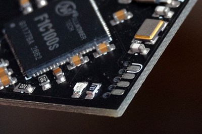
Finally, [Jay] shows off a couple of test projects, including a NeoPixel SPI adapter and bike light, which are all available on Github. The WS2812b project is something we have seen before, for example this project from [Anders Nielsen] (featured in the article image), which provides another take on this range of MCUs.
Did reading [Jay]’s article change your mind on these Padauk parts? Have you used these MCUs and ICE parts before? Feel free to leave your thoughts in the comments.
Just a section from a render of the board in question. It’s a daunting task for anyone facing it with a set of tweezers or a vacuum pencil.
A friend of ours here at Hackaday has an audacious design in the works that we hope will one day become a prototype that we can feature here. That day may be a little while coming though, because it has somewhere close to a thousand of the smaller SMD components in multiple repeated blocks on a modestly sized board, and his quote from a Chinese board house for assembly is eye-watering. He lacks a pick-and-place machine of his own, and unsurprisingly the idea of doing the job by hand is a little daunting.
We can certainly feel his pain, for in the past we’ve been there. The job described in the linked article had a similar number of components with much more variety and on a much larger board, but still took two experienced engineers all day and into the night to populate. The solder paste had started to spread by the end, morphing from clearly defined blocks to an indistinct mush often covering more than one pad. Our eyes meanwhile were somewhat fatigued by the experience, and it’s not something any sane person would wish to repeat.
Mulling over our friend’s board and comparing it with the experience related above, are we on the edge of what is possible with hand pick-and-place, or should we be working at the next level? Board assembly is a finely judged matter of economics at a commercial level, but when at a one-off personal construction level the option of paying for assembly just isn’t there, is there a practical limit to the scale of the task? Where do you, our readers, draw the line? We’d love to hear your views.
Meanwhile our friend’s audacious project is still shrouded in a bit of secrecy, but we’ll continue to encourage him to show it to the world. It’s not often that you look at a circuit diagram and think “I wish I’d thought of that!”, but from what we’ve seen this fits the category. If he pulls it off then we’ll bring you the result.
When [Freddie] was faced with the challenge of building a sendoff gift for an an LED-loving coworker he hatched a plan. Instead of making a display from existing video wall LED panels he would make a cube. But not just any cube, a miniature desk sized one that wasn’t short of features or performance. We’d be over the moon if someone gifted us with this itty-bitty Qi coil-powered masterpiece of an RGB cube.
Recently we’ve been blessed with a bevy of beautiful, animatedRGBcubes but none hit quite this intersection of size and function. The key ingredient here is tiny but affordable RGB LEDs which measure 1 mm on a side. But LEDs this small are dwarfed by the otherwise minuscule “2020” package WS2812’s and APA102s of the world. Pushing his layout capabilities to the max [Freddie] squeezed each package together into a grid with elements separated by less than 1 mm, resulting in a 64 LED panel that is only 16 mm x 16 mm panel (with test points and controller mounted to the back). Each of these four-layer PCBs that makes up the completed cube contains an astonishing 950 mm of tracking, meaning the entire cube has nearly six meters of traces!
How do you power such a small device with no obvious places to locate a connector? By running magnet wire through a corner and down to a Qi coil of course. Not to let the cube itself outshine the power supply [Freddie] managed to deadbug a suitably impressive supply on the back of the coil itself. Notice the grain of rice in the photo to the left! The only downside here is that the processor – which hangs diagonally in the cube on a tiny motherboard – cannot be reprogrammed. Hopefully future versions will run programming lines out as well.
Check out the video of the cube in action after the break, and the linked photo album for much higher resolution macro photos of the build. While you’re there take a moment to admire the layout sample from one of the panels! If this sets the tone, we’re hoping to see more of [Freddie]’s going-away hacks in the future!
It probably goes without saying that hardware hackers were excited when the Raspberry Pi 4 was announced, but it wasn’t just because there was a new entry into everyone’s favorite line of Linux SBCs. The new Pi offered a number of compelling hardware upgrades, including an onboard PCI-Express interface. The only problem was that the PCIe interface was dedicated to the USB 3.0 controller; but that’s nothing a hot-air rework station couldn’t fix.
Getting that first PCIe port added to the Pi 4 is already fairly well understood, so [Colin] just had to follow the example set by hackers such as [Tomasz Mloduchowski]. Sure enough, when he plugged the port multiplier board in (after a bit of what he refers to as “professional wiggling”), the appropriate entry showed up in lspci.
But there was a problem. While the port multiplier board was recognized by the kernel, nothing he plugged into it showed up. Checking the kernel logs, he found messages relating to bus conflicts, and one that seemed especially important: “devices behind bridge are unusable because [bus 02] cannot be assigned for them“. To make a long story short, it turns out that the Raspbian kernel is specifically configured to only allow a single PCI bus.
Fortunately, it’s an easy fix once you know what the problem is. Using the “Device Tree Compiler” tool, [Colin] was able to edit the Raspbian Device Tree file and change the PCI “bus-range” variable from <0x0 0x1> to <0x0 0xff>. From there, it was just a matter of plugging in different devices and seeing what works. Simple things such as USB controllers were no problem, but getting ARM Linux support for the NVIDIA GTX 1060 he tried will have to be a topic for another day.