Let’s face it: cutting foam with a knife, even a serrated plastic knife meant for the job, is a messy pain in the ass. This is as true for insulation board as it is for the ubiquitous expanded polystyrene kind of foam used for everything from coffee cups to packaging material.
Those stick-type hot wire cutters from the craft store that plug into the wall aren’t much better than a knife. The actual cleaving of foam is easier, but dragging a long, hot flexible wand through rigid foam just right, without making burn marks, is pretty frustrating. It’s not like you can hold the other end to keep it steady. A foam cutter built like a coping saw but held parallel to the wire would offer much better control.
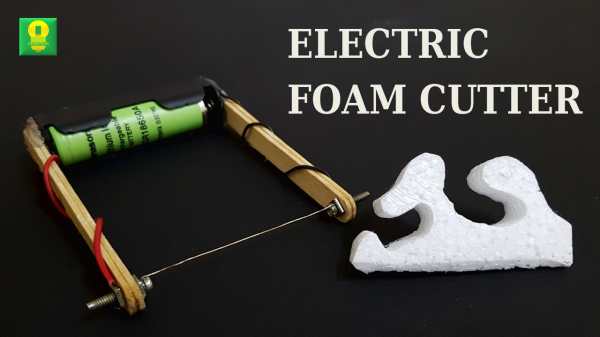
[Techgenie]’s handheld hot wire foam cutter is a simple build based on a single 18650 and a piece of nichrome wire. While this is probably not the most Earth-shattering hack you’ll see today, it’s a useful tool that can be made in minutes with items on hand. Laptop chargers are full of 18650s, and nichrome wire can be sourced from old toasters, hair dryers, or space heaters.
You shouldn’t use just any old wire for this, though, or the battery will get hot and potentially explode. Nichrome wire has a high resistance, and that’s exactly what you want in a tool that essentially shorts a battery to make heat. [Techgenie] used a momentary button instead of a switch, which is a good way to stay safe while using it. It wouldn’t hurt to add some protection circuitry and take the battery out when you’re done. Burn past the break to watch him build it and cut a few tight turns with ease.
If you have bigger, more complicated foam-cutting jobs in mind, why not build a CNC version out of e-waste?


 A delightful version of a clever one-dimensional game has been made by [Critters] which he calls