Storm Detector Modules: Dancing In The Rain

Earlier, we had covered setting up an AS3935 lightning detector module. This detector picks up radio emissions, then analyzes them to determine if they are a lightning strike or some other radio source. After collecting some data, it outputs the estimated distance to the incoming storm front.

But that only gets you halfway there. The device detects many non-lightning events, and the bare circuit board is lacking in pizzazz. Today I fix that by digging into the detector’s datasheet, and taking a quick trip to the dollar store buy a suitable housing. The result? A plastic plant that dances when it’s going to rain!
Continue reading “Storm Detector Modules: Dancing In The Rain”

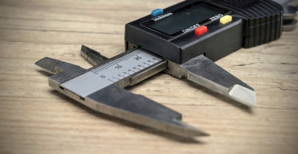
How To Reverse Engineer Mechanical Designs For 3D Modeling

If you’re interested in 3D printing or CNC milling — or really any kind of fabrication — then duplicating or interfacing with an existing part is probably on your to-do list. The ability to print replacement parts when something breaks is often one of the top selling points of 3D printing. Want some proof? Just take a look at what people made for our Repairs You Can Print contest.

Of course, to do that you need to be able to make an accurate 3D model of the replacement part. That’s fairly straightforward if the part has simple geometry made up of a primitive solid or two. But, what about the more complicated parts you’re likely to come across?

In this article, I’m going to teach you how to reverse engineer and model those parts. Years ago, I worked for a medical device company where the business model was to duplicate out-of-patent medical products. That meant that my entire job was reverse engineering complex precision-made devices as accurately as possible. The goal was to reproduce products that were indistinguishable from the original, and because they were used for things like trauma reconstruction, it was critical that I got it right.

Continue reading “How To Reverse Engineer Mechanical Designs For 3D Modeling”

DIY Perpetual Flip Calendar

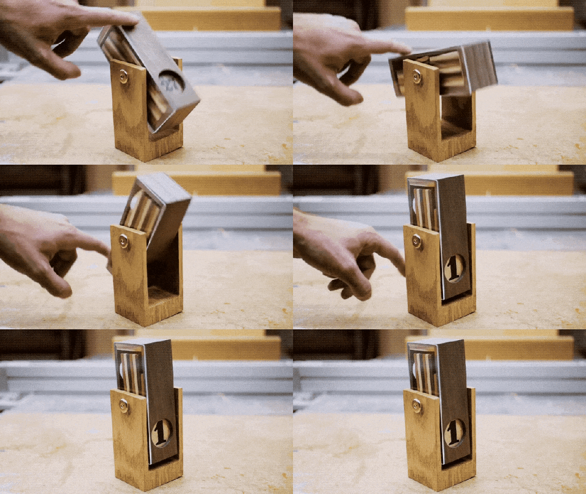
Flip calendars are a neat little piece of history. Sold as tourist trinkets, they sit on your desk and show the current day of the month and, depending on the particular calendar, month and year. Each day, you rotate it and it shows you the current date. At the end of February, you rotate it a bunch of times to get from February 28th (or 29th) to March 1st. [measuredworkshop] always had fun flipping the dates on his parents’ flip calendar, so decided to build his own wooden one.

The calendars consist of a series of tiles with the dates on them inside an enclosure. Rotating the enclosure allows a new tile to slide down in front of the old one. Once you know how many tiles you are going to use, you put a different date on the back side of each tile. In [measuredworkshop]’s case, there were 15 tiles to hold 30 dates (he created one with 30/31 on it for the end of the month) so the 1 has a 16 on the back, the 2 a 17, and so on. Tiles of different colored wood were cut and sanded and then the numbers drawn on by hand.

The enclosure was cut using a Morso Guillotine, a machine which uses sharp blades to do precise mitre cuts in wood. One side of the enclosure was covered by wood, the other by clear acrylic, so that you can see how the mechanism works as it is rotated. Finally, a stand was cut from wood as well and the final product assembled.

As you can see in the video below this is a great showpiece, and because of the design gives a view into how flip-calendars work. At the end of his write-up, [measuredworkshop] shares a link he found to a 3d printed flip-calendar on Thingiverse. Check out some of the more techie calendars posted at Hackaday, like this e-ink calendar, or this Raspberry Pi wall calendar.

Continue reading “DIY Perpetual Flip Calendar”

An Introduction To Storm Detector Modules

Lightning storm detectors have been around for a surprisingly long time. The early designs consisted of a pair of metal bells and a pendulum. When there was a charge applied, for example by connecting one bell to the ground and the other to a lightning rod, the bells would ring when a lightning storm was close by. In the mid 18th century, these devices were only practical for demonstration and research purposes, but very likely represent the earliest devices that convert electrostatic charge to mechanical force. A bit over a hundred years later, the first lightning detector was considered by some as the first radio receiver as well.

As soon as I found out about storm detector chips, I knew I would have to get one working. For about $25, I ordered an AMS AS3935 module from China. This chip has been featured before in a number of excellent projects such as Twittering lightning detectors, and networks of Sub-Saharan weather stations. While there’s an Arduino library for interfacing with this IC, I’m going to be connecting it up to an ESP8266 running the NodeMCU firware, which means digging into the datasheet and writing some SPI code. If any of the above tickles your fancy, read on! Continue reading “An Introduction To Storm Detector Modules”

What To Do With Your Brand New Ultrasonic Transducer

We wager you haven’t you heard the latest from ultrasonics. Sorry. [Lindsay Wilson] is a Hackaday reader who wants to share his knowledge of transducer tuning to make tools. The bare unit he uses to demonstrate might attach to the bottom of an ultrasonic cleaner tank, which have a different construction than the ones used for distance sensing. The first demonstration shows the technique for finding a transducer’s resonant frequency and this technique is used throughout the video. On the YouTube page, his demonstrations are indexed by title and time for convenience.

For us, the most exciting part is when a tuned transducer is squeezed by hand. As the pressure increases, the current drops and goes out of phase in proportion to the grip. We see a transducer used as a pressure sensor. He later shows how temperature can affect the current level and phase.

Sizing horns is a science, but it has some basic rules which are well covered. The basic premise is to make it half of a wavelength long and be mindful of any tools which will go in the end. Nodes and antinodes are explained and their effects demonstrated with feedback on the oscilloscope.

We have a recent feature for an ultrasonic knife which didn’t cut the mustard, but your homemade ultrasonic tools should be submitted to our tip line.

Continue reading “What To Do With Your Brand New Ultrasonic Transducer”

Making Pictures Worth 1000 Words In Python

In a previous post, I showed how you could upload images into a Discord server from Python; leveraging the popular chat platform to simplify things like remote monitoring and push notifications on mobile devices. As an example, I showed an automatically generated image containing the statistics for my Battlefield 1 platoon which gets pushed to member’s devices on a weekly basis.

Automatically generated stats posted to Discord

The generation of that image was outside the scope of the original post, but I think it’s a technique worth discussing on its own. After all, they say that a picture is worth 1000 words. So that means a picture that actually contains words must be worth way more. Like, at least 2000, easy.

Being able to create images from your textual data can lend a bit of flair to your projects without the need to create an entire graphical user interface. By putting a text overlay on a pre-rendered image, you can pull off some very slick visuals with a minimum amount of system resources. So long as you have a way of displaying an image file, you’re good to go.

In this post I’ll quickly demonstrate how to load an image, overlay it with text, and then save the resulting image to a new file. This technique is ideal in situations where a display doesn’t need to be updated in real-time; visuals can be generated at regular intervals and simply displayed as static images. Possible uses include weather displays, “magic” mirrors, public signage, etc. Continue reading “Making Pictures Worth 1000 Words In Python”

Curved Wood LED Lamp Needs No Fancy Tools

Those of us who aren’t familiar with woodworking might not expect that this curved wood and acrylic LED lamp by [Marija] isn’t the product of fancy carving, just some thoughtful design and assembly work. The base is a few inches of concrete in a plastic bowl, then sanded and given a clear coat. The wood is four layers of beech hardwood cut on an inverted jigsaw with the middle two layers having an extra recess for two LED strips. After the rough-cut layers were glued together, the imperfections were rasped and sanded out. Since the layers of wood give a consistent width to the recess for the LEDs, it was easy to cut a long strip of acrylic that would match. Saw cutting acrylic can be dicey because it can crack or melt, but a table saw with a crosscut blade did the trick. Forming the acrylic to match the curves of the wood was a matter of gentle heating and easing the softened acrylic into place bit by bit.

Giving the clear acrylic a frosted finish was done with a few coats of satin finish clear coat from a spray can, which is a technique we haven’t really seen before. Handy, because it provides a smooth and unbroken coating along the entire length of the acrylic. This worked well and is a clever idea, but [Marija] could still see the LEDs and wires inside the lamp, so she covered them with some white tape. A video of the entire process is embedded below.

Continue reading “Curved Wood LED Lamp Needs No Fancy Tools”