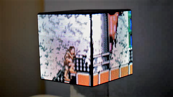
Let’s Look At Some Cool Old LEDs

LEDs are now a mature technology, with all manner of colors and flavors available. However, back in the 1970s, it was early days for this fledgling display tech, and things looked very different. [IMSAI Guy] happened to work at the optoelectronics division of Hewlett-Packard during their development of LED displays, and has a handful of prototypes from those heady days.

The video is a great look at not only vintage display hardware, but also rarely seen prototypes that seldom left the HP offices. Matrix, 7-segment and even 16-segment devices are all in attendance here. There’s great macro photography of the packages, including the now-forgotten bubble displays as well as hermetically sealed glass packages. The parts all have a uniquely 1970s look, drenched in gold plating and otherwise just looking very expensive.

The followup video breaks out the microscope and powers up the displays. [IMSAI Guy] shares some useful tips on how to best tinker with unknown LED parts, as well as knowledge about the chemical compounds and manufacturing processes involved in LED production. If you don’t know your III-V compounds from your II-VI compounds, prepare to learn.

It’s always interesting to take a look back, and even better to get a peek at the experiments of engineers of the past.

If you’re wondering about applications of this hardware, we’ve seen messageboards and watches before. Video after the break.

Continue reading “Let’s Look At Some Cool Old LEDs”

Christmas POV Display Makes Viewer Do The Work

Hackaday readers have certainly seen more than a few persistence of vision (POV) displays at this point, which usually take the form of a spinning LED array which needs to run up to a certain speed before the message becomes visible. The idea is that the LEDs rapidly blink out a part of the overall image, and when they get spinning fast enough your brain stitches the image together into something legible. It’s a fairly simple effect to pull off, but can look pretty neat if well executed.

But [Andy Doswell] has recently taken an interesting alternate approach to this common technique. Rather than an array of LEDs that spin or rock back and forth in front of the viewer, his version of the display doesn’t move at all. Instead it has the viewer do the work, truly making it the “Chad” of POV displays. As the viewer moves in front of the array, either on foot or in a vehicle, they’ll receive the appropriate Yuletide greeting.

In a blog post, [Andy] gives some high level details on the build. Made up of an Arduino, eight LEDs, and the appropriate current limiting resistors on a scrap piece of perfboard; the display is stuck on his window frame so anyone passing by the house can see it.

On the software side, the code is really an exercise in minimalism. The majority of the file is the static values for the LED states stored in an array, and the code simply loops through the array using PORTD to set the states of all eight digital pins at once. The simplicity of the code is another advantage of having the meatbag human viewer figure out the appropriate movement speed on their own.

This isn’t the only POV display we’ve seen with an interesting “hook” recently, proving there’s still room for innovation with the technology. A POV display that fits into a pen is certainly a solid piece of engineering, and there’s little debate the Dr Strange-style spellcaster is one of the coolest things anyone has ever seen. And don’t forget Dog-POV which estimates speed of travel by persisting different images.

[Thanks to Ian for the tip.]

An Over-engineered LED Sign Board

Never underestimate the ability of makers in over thinking and over-engineering the simplest of problems and demonstrating human ingenuity. The RGB LED sign made by [Hans and team] over at the [Hackheim hackerspace] in Trondheim is a testament to this fact.

As you would expect, the WS2812 RGB LEDs illuminate the sign. In this particular construction, an individual strip is responsible for each character. Powered by an ESP32 running FreeRTOS, the sign communicates using MQTT and each letter gets a copy of the 6 x 20 framebuffer which represents the color pattern that is expected to be displayed. A task on the ESP32 calculates the color value to be displayed by each LED.

The real question is, how to calibrate the distributed strings of LEDs such that LEDs on adjacent letters of the sign display an extrapolated value? The answer is to use OpenCV to create a map of the LEDs from their two-dimensional layout to a lookup table. The Python script sends a command to illuminate a single LED and the captured image with OpenCV records the position of the signal. This is repeated for all LEDs to generate a map that is used in the ESP32 firmware. How cool is that?

And if you are wondering about the code, it is up on [Github], and we would love to see someone take this up a level. The calibration code, as well as the Remote Client and ESP32 codes, are all there for your hacking pleasure.

Its been a while since we have seen OpenCV in action like with the Motion Tracking Turret and Face Recognition. The possibilities seem endless. Continue reading “An Over-engineered LED Sign Board”

Negative Voltage Pushes AVR To New Heights

If we say that a hacker is somebody who looks at a “solved” problem and can still come up with multiple alternative solutions, then [Charles Ouweland] absolutely meets the grade. Not that we needed more evidence of his hacker cred given what we’ve seen from him before, but he recently wrote in to tell us about an interesting bit of problem solving which we think is a perfect example of the principle. He wanted to drive a salvaged seven segment LED display with an AVR microcontroller, but there was only one problem: the display needs 15V but the AVR is only capable of 5V. So what to do?

As it turns out, the first step to solving the problem was verifying there was actually a problem to begin with. [Charles] did some experimentation and found that the display didn’t actually need 15V to operate, and in fact would light up well enough at just 6.5V. This lowered the bar quite a bit, but it was still too high to power directly from the chip.

There were a few common ways to solve this problem, which no doubt the Hackaday reader is well aware of. But [Charles] wanted to take the path less traveled. More specifically, the path with the least amount of additional components he had to put on his PCB. He set out to find the absolute easiest way to make his 5V AVR light up a 6.5V LED, and ended up coming with a very clever solution that some may not even know is possible.

He reasoned that if he connected the source pins of two BS170 MOSFETs to a voltage of -1.5V, even when the AVR pin was 0V, they would be still be receiving 1.5V. This virtual “step ladder” meant that once the AVR’s pin goes high (5V), the relative voltage would actually be 6.5V and enough to drive his LEDs. Of course the only problem with that is that you need to have a source for -1.5V.

Getting a negative voltage would normally require adding more components to the design (which he set out to avoid in the first place), but then he came up with another clever idea. To pull the trick off, he actually feeds the AVR 6.5V, but raises the ground voltage by 1.5V with the addition of two 1N4007 diodes. This way the AVR gets a voltage within its capabilities and still can provide a relative 6.5V to the LEDs.

One might say [Charles] took the Kobayashi Maru approach, and simply redefined the rules of the game. But such is the power of the confounding negative voltage.

Solar Heart Engineered To Beat For Decades

It’s often said that if something is worth doing it’s worth doing right, or maybe even worth overdoing. This is clearly a concept that [ANTALIFE] takes very seriously, as made abundantly clear by projects like the solar powered “beating” heart he made as a gift for his wife. What for most of us would have ended up being a junk bin build becomes a considerable engineering project in his hands, with a level of research and fine tuning that’s frankly staggering.

But [ANTALIFE] didn’t put this much thought into the device just for fun. He wants it to remain functional for as long as 30 years, and hopes he and the missus can still look on it fondly in their retirement years. Keeping an electronic device up and running for decades straight means you need to look carefully at each component and try to steer clear of any potential pitfalls.

The biggest one was the battery. More specifically, the fact he couldn’t use one. The lifetime of most rechargeable batteries is measured in hundreds of cycles, which for a device which will be charged by solar every day, means the battery is going to start showing its age in only 4 to 5 years. That simply wasn’t going to cut it.

[ANTALIFE] did some digging and realized that the solution was to use a supercapacitor, specifically the AVX SCMS22C255PRBA0. This is little wonder is rated for a staggering half million cycles, which in theory means that even with daily use it should still take a charge in the year 3300. In practice of course there are a lot of variables which will reduce that lifetime such as temperature fluctuations and the Earth being conquered by apes; but no matter what caveats you put on the figure it should still make 30 years without breaking a sweat.

Similar thought was given to choosing a solar cell with a suitably long lifetime, and he did plenty of testing and experimentation with his charging circuit, including some very nice graphs showing efficiency over time, to make sure it was up to snuff. Finally he walks the reader though his light-sensitive ring oscillator circuit which gives the device its pleasing “breathing” effect once the lights go down.

We’d love to bring you an update on this device in 30 years to see how close [ANTALIFE] got, but as we’re still trying to work the kinks out of the mobile version of the site we can’t make any guarantees about what the direct-brain interface version of HaD might look like. In the meantime though, you can read up on the long term battle between supercapacitors and traditional batteries.

Continue reading “Solar Heart Engineered To Beat For Decades”

A Neat Pen POV Build

We’ve seen a lot of persistence of vision (POV) builds on bike wheels, sticks, and many other holders, but this one puts it on something new: a pen. [Befinitiv] was looking for a new way to add some smarts to everyday devices, and the result is a neat POV display that fits over a pen. At 128 by 64 pixels, it is not high definition, but this build uses a number of interesting techniques.

Continue reading “A Neat Pen POV Build”

A Guide For Driving LED Matrices

Building an LED matrix is a fun project, but it can be a bit of a pain. Usually it starts with hand-soldering individual LEDs and resistors together, then hooking them up to rows and columns so they can be driven by a microcontroller of some sort. That’s a lot of tedious work, but you can order an LED matrix pre-built to save some time and headache. You’ll still need a driver though, and while building one yourself can be rewarding there are many pitfalls and trade-offs to consider when undertaking that project as well. Or, you can consider one of a number of drivers that [deshipu] has outlined in detail.

The hangups surrounding the driver board generally revolve around the issue of getting constant brightness from LEDs regardless of how many in the row or column are illuminated at one time. Since they are typically driven one row or column at a time, the more that are on the lower the brightness each LED will have. Driver boards take different approaches to solving this problem, which usually involve a combination of high-speed scanning of the matrix or using a constant-current source in order to eliminate the need for resistors. [deshipu] outlines four popular chips that achieve these purposes, and he highlights their pros and cons to help anyone looking to build something like this.

Most of these boards will get you to an 8×8 LED matrix with no problem, with a few going a few pixels higher in either direction. That might be enough for most of our needs, but for something larger you’ll need other solutions like the one found in this 64×32 LED matrix clock. There are also even more complicated drivers if you go into extra dimensions.

Photo credit: Komatta [Public domain], from Wikimedia Commons