Emulating OBD-II On The ESP32

It used to be that you could pop the hood and with nothing more than flat head screwdriver, some baling wire, and tongue held at the optimal angle, you could fix anything that ailed your car. But today, for better or for worse, the average automobile is a rolling computer that runs on gasoline and hope (if it even still has a gasoline engine, that is). DIY repairs and maintenance on a modern car is still possible of course, but the home mechanic’s toolbox has needed to evolve with the times. If you want to do anything more advanced than changing a tire, you’ll really want to have the gear to interface with the vehicle’s computer via the OBD-II port.

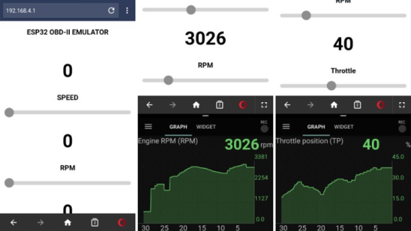
But for some, even that isn’t enough. [limiter121] recently wrote in to tell us of an interesting project which doesn’t read the OBD-II port in a vehicle, but actually emulates one. Like so many others this hack was born out of necessity, as a way to test an OBD-II project without having to sit out in the driveway all day. It allows you to create fictitious speed and engine RPM values for the OBD-II device or software under test to read, complete with a slick web interface to control the “car”.

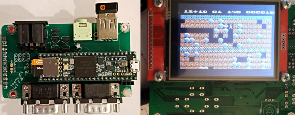
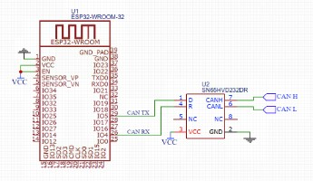
So what makes it tick? Surprisingly little, actually. At the most basic level, an ESP32-WROOM-32 is connected up to a SN65HVD230 CAN transceiver chip. You’ll also need a 3.3V power supply, as well as a USB to serial adapter to do the initial programming on the ESP32. From there it’s just a matter of compiling and flashing the code [limiter121] has made available in the GitHub repo.

If you’re wondering if such products don’t already exist on the commercial market, they do. But like so many other niche projects, the price is a bit hard to swallow for the home hacker. Compared to the nearly $300 USD list price of commercial offerings such as the Freematics OBD-II Emulator, building one of these ESP32 based emulators should only cost you around $20.

Unless you’re developing an OBD-II reader, you probably don’t have much use for an OBD-II emulator. But this project could still be useful for anyone who wants to learn more about OBD from the comfort of their couch.

New App Note Day: Internet Of Pillows

The Internet of Things is a cancer that consumes all reasonable expectations of technology, opens vast security holes we’ve never had to deal with before, and complicates life in the pursuit of quarterly gains from whatever technology startup is hot right now. We are getting some interesting tech out of it, though. The latest in the current round of ‘I can’t believe someone would build that’ is the Internet of Pillows. No, it’s not a product, it’s just an application note, but it does allow us to laugh at the Internet of Things while simultaneously learning about some really cool chips.

The idea behind this ‘smart’ pillow is to serve as a snoring sensor. When the smart pillow detects the user is snoring, a small vibration motor turns on to wake up the user. There’s no connectivity in this smart pillow, so the design is relatively straightforward. You need a microphone or some sort of audio sensor, you should probably have a force-sensitive resistor so you know the pillow is actually being used, and you need a vibration motor. Throw in a battery for good measure. Aside from that, you’re also going to need a microcontroller, and that’s where things get interesting.

This application note was written as a demonstration of what Dialog’s GreenPAC devices can do. We’ve seen these things before, and the idea behind these devices is something like a ‘modern-day PAL’ or ‘a really, really limited FPGA’. It’s a bit more than that, though, because the GreenPAC devices are mixed-signal, there are some counters and latches in there, and all the programming is done through a graphical IDE. If you need a small, low-power chip that only does one thing, the GreenPAC is right up your alley.

So, how does this device detect snoring? The code pulls data from the sound sensor every 30 ms, with a 5 ms time window. If this sound repeats again within six seconds, it’s assumed the user is snoring. The logic then turns on the vibration motor, greatly annoying whoever is sleeping. All of this is done through a graphical IDE, which I’m sure will draw the ire of some, but there really aren’t that many pins or that many LUTs on GreenPAC devices, so it’s never going to get too out of hand.

The GreenPAC is a very interesting family of parts that we don’t see too much of around here. That’s a shame, because for low-power applications that don’t need a lot of horsepower, the GreenPAC seems like it would be very useful. Slightly more useful than an Internet of Things pillow, at least.

Reviving An Electron Microscope With Arduino

We don’t know about you, but when our friends ask us if we want to help them fix something, they’re usually talking about their computer, phone, or car. So far it’s never been about helping them rebuild an old electron microscope. But that’s exactly the request [Benjamin Blundell] got when a friend from a local hackerspace asked if he could take a look at a vintage Cambridge Stereoscan 200 they had found abandoned in a shed. Clearly we’re hanging out with the wrong group of people.

As you might imagine, the microscope was in desperate need of some love after spending time in considerably less than ideal conditions. While some of the hackerspace members started tackling the hardware side of the machine, [Benjamin] was tasked with finding a way to recover the contents of the scope’s ROM. While he’s still working on verification, the dumps he’s made so far of the various ROMs living inside the Stereoscan 200 have been promising and he believes he’s on the right track.

The microscope uses a mix of Texas Instruments 25L32 and 2516 chips, which [Benjamin] had to carefully pry out after making sure to document everything so he knew what went where. A few of the chips weren’t keen on being pulled from their home of 30-odd years, so there were a few broken pins, but on the whole the operation was a success.

Each chip was placed in a breadboard and wired up to an Arduino Mega, as it has enough digital pins to connect without needing a shift register. With the wiring fairly straightforward, [Benjamin] just needed to write up some code to read the contents of the chip, which he has graciously provided anyone else who might be working on a similar project. At this point he hasn’t found anything identifiable in his ROM dumps to prove that they’ve been made successfully, all he really knows right now is that he has something. At least it’s a start.

More and more of these older electron microscopes are getting a second lease on life thanks to dedicated hackers in their home labs. Makes you wonder if there’s ever going to be a piece of hardware the hacker community won’t bend to their will.

Kniwwelino Is An ESP8266 Micro:Bit

Kniwwelino is the latest in a line of micro:bit-inspired projects that we’ve seen, but this one comes with a twist: it uses an ESP8266 and WiFi at the core instead of the nR51 ARM/BTLE chip. That means that students can connect via laptop, cellphone, or anything else that can get onto a network.

That’s not the only tradeoff, though. In order to get the price down, the Kniwwelino drops the accelerometer/magnetometer of the micro:bit for a programmable RGB LED. With fewer pins to break out, the Kniwwelino is able to ditch the love-it-or-hate-it card-edge connector of the micro:bit as well. In fact, with all these changes, it’s hard to call this a micro:bit clone at all — it’s more like a super-blinky ESP8266 development kit.

So what have they got left in common? The iconic 5×5 LED matrix in the center, and a Blockly visual programming dialect dedicated to the device. Based on the ESP8266, the Kniwwelino naturally also has an Arduino dialect that students can “graduate” to when they’re tired of moving around colored blobs, and of course you could flash the chip with anything else that runs on an ESP8266.

We don’t have one in our hands, but we like the idea. An RGB LED is a lot of fun on Day One, and the fact that the Kniwwelino fits so neatly into existing bodies of code makes the transition from novice to intermediate programmer a lot easier. These things are personal preference, but WiFi beats Bluetooth LE in our book, for sheer ubiquity and interoperability. Finally, the Kniwwelino comes in at about half the manufacturing cost of a micro:bit, which makes it viable in schools without large manufacturer subsidies. They’re estimating $5 per unit. (Retail is higher.) On the other hand, the Kniwwelino is going to use more juice than its ARM-based competitor, and doesn’t have an accelerometer.

Kniwwelino is apparently derived from a luxembourgish word “kniwweln” that apparently means to craft something. The German Calliope Mini is named after Zeus’ daughter, the programmer’s muse. We’re stoked to see so many cute dev boards getting into the hands of students, no matter what you call them.

Emulating A Complete Commodore 64

When the Commodore 64 was released in 1982, it was a masterpiece of engineering. It had capabilities far outstripping other home computers, and that was all due to two fancy chips inside the C64. The VIC-II, the video chip for the C64, had sprites and scrolling, all stuffed into a single bit of silicon. The SID chip was a complete synthesizer on a chip. These bits of silicon made the C64 the best selling computer of all time, but have also stymied efforts to emulate a complete C64 system on a microcontroller.

[Frank Bösing] has just managed to emulate an entire C64 on a Teensy 3.6. The Teensy uses an exceptionally powerful microcontroller, but this is a labor of love and code.

The inspiration for this project comes from a reverse-engineered SID chip that was ported to the Teensy 3.2. The SID chip is the make it or break it feature of any C64 emulation, but the Teensy 3.2 didn’t have enough RAM for the most recent versions of reSID. With the release of the Teensy 3.6, [Frank] figured the increased amount of RAM would allow a complete C64 system, so he built it.

The new C64 emulator uses a Teensy 3.6, with a small add-on ‘shield’ (or whetever we’re calling them) to provide connectors for joysticks and the Commodore IEC bus. There’s audio out, support for USB keyboards, and support for an IL9341 SPI display or a regular ‘ol VGA display.

The entire development of this Commodore emulator has been documented over on the PJRC forums, and all the code is over on GitHub. It’s a fantastic piece of work, and as the video (below) shows, this is a real Commodore 64 that fits in your pocket.

Continue reading “Emulating A Complete Commodore 64”

Evolution Of The ESP8266 Party Button

Sometimes the best part of building something is getting to rebuild it again a little farther down the line. Don’t tell anyone, but sometimes when we start a project we don’t even know where the end is going to be. It’s a starting point, not an end destination. Who wants to do something once when you could do it twice? Maybe even three times for good measure?

Original version of the Party Button

That’s what happened when [Ryan] decided to build a wireless “party button” for his kids. Tied into his Home Assistant automation system, a smack of the button plays music throughout the house and starts changing the colors on his Philips Hue lights. His initial version worked well enough, but in the video after the break, he walks through the evolution of this one-off gadget into a general purpose IoT interface he can use for other projects.

The general idea is pretty simple, the big physical button on the top of the device resets the internal ESP8266, which is programmed to connect to his home WiFi and send a signal to his MQTT server. In the earlier versions of the button there was quite a bit of support electronics to handle converting the momentary action of the button to a “hard” power control for the ESP8266. But as the design progressed, [Ryan] realized he could put the ESP8266 to deep sleep after it sends the signal, and just use the switch to trigger a reset on the chip.

Additional improvements in the newer version of the button include switching from alkaline AA batteries to a rechargeable lithium-ion pack, and even switching over to a bare ESP8266 rather than the NodeMCU development board he was using for the first iteration.

For another take on MQTT home automation with the ESP8266, check out this automatic garage door control system. If the idea of triggering a party at the push of a button has your imagination going, we’ve seen some elaborate versions of that idea as well.

Continue reading “Evolution Of The ESP8266 Party Button”

3D Printed ESP8266 Programming Jig

The various development boards such as the NodeMCU or Wemos D1 make working with the ESP8266 an absolute breeze. If they have a downside, it is that they are larger than the bare ESP2866, and of course cost a bit more. Just as with the Arduino, once you have the wiring sorted out and the code more or less finalized, your best bet is to ditch the unnecessary support hardware and use the bare module to save space and money in your final design.

The design took a few revisions to get right

Unfortunately, the ESP8266 form factor isn’t terribly forgiving when it comes time for hooking up a programmer. Rather than having to solder a serial adapter to the chip to flash it, [Ryan] came up with a slick 3D printed programming jig that uses pogo pins. If you have to program these boards in bulk, a jig like this can save a massive amount of time and aggravation.

Beyond the 3D printed holder for the pogo pins, this programmer uses a FTDI USB-to-serial adapter, a couple passive components to smooth out the power going into the chip, and a couple buttons.

In the video after the break, [Ryan] walks through the many iterations it took to get the 3D printed aspect of the jig worked out. The design went through a few rather large revisions, including one that fundamentally changed the whole form factor. Even with the jig now working, he mentions that he might circle back around and try it from a different angle.

Programming jigs are a staple of electronics manufacturing, and we’ve covered quite a few that have helped transformed a proof of concept into a small scale production runs.

Continue reading “3D Printed ESP8266 Programming Jig”