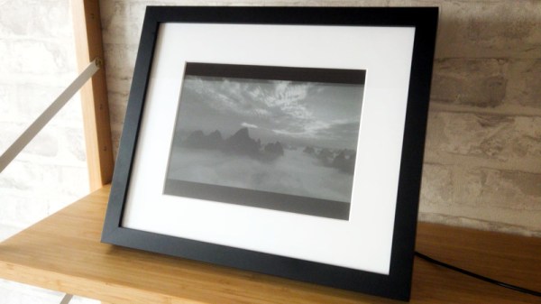
Just like the clock clock of old, there’s something magical about a giant wall of smaller pieces working together to make a larger version of that thing. The E-Paper Wall 2.0 by [Aaron Christophel] is no exception as it has now upgraded from 2.9″ to 7.4″ screens.
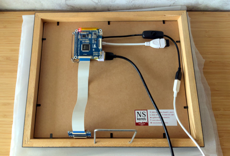
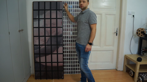
On the 1.0 version, the bezels made it harder to make out the image. The larger screens still have bezels but the larger screen area makes it much easier to make out the image. 3D-printed clips hold the displays onto a plywood backer. We can marvel that e-ink price tags brought the price of e-ink down so that building a wall is still expensive but not eye-wateringly so. The 5×9 array likely uses a module sold on DigiKey for $47 each.
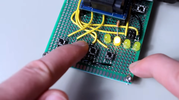
So aside from being willing to drop some money on a custom piece of art, what’s special about this? The real magic comes with the firmware and tooling that [Aaron] developed to flash custom firmware onto each of the 45 displays. A 100MHz ZBS243/SEM9110 8051-based controller lives inside each display and [Aaron] even has a Ghidra plugin to reverse-engineer the existing firmware. It only has 64kb of flash onboard, so [Aaron] devised a clever compression technique that enabled him to store complex images on the displays. A 3D-printed jig with pogo pins means flashing them doesn’t require soldering pins or headers, just drop it on and flash it with an Arduino with a helpful library [Aaron] wrote. A central station communicates with the various displays over ZigBee to send image updates.
The 8051 has a funny way of showing up in projects like this portable soldering iron or the TV Guardian. In many ways, it is a boon for us hackers as it makes it easier to reverse engineer and write new custom firmware when so many devices use the same architecture.