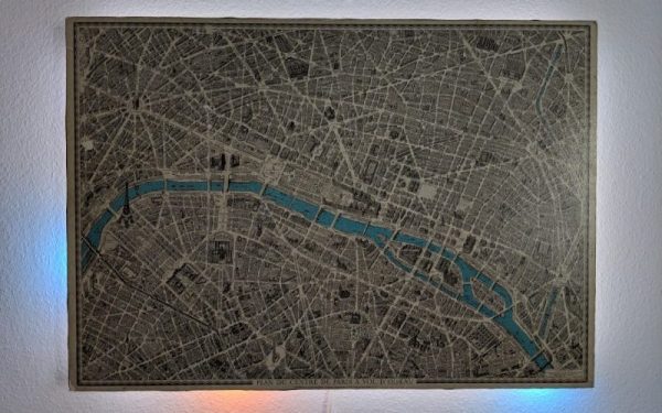
The Shell And The Microcontroller

One of the nicest amenities of interpreted programming languages is that you can test out the code that you’re developing in a shell, one line at a time, and see the results instantly. No matter how quickly your write-compile-flash cycle has gotten on the microcontroller of your choice, it’s still less fun than writing blink_led() and having it do so right then and there. Why don’t we have that experience yet?

If you’ve used any modern scripting language on your big computer, it comes with a shell, a read-eval-print loop (REPL) in which you can interactively try out your code just about as fast as you can type it. It’s great for interactive or exploratory programming, and it’s great for newbies who can test and learn things step by step. A good REPL lets you test out your ideas line by line, essentially running a little test of your code every time you hit enter.

This is your development environment

The obvious tradeoff for ease of development is speed. Compiled languages are almost always faster, and this is especially relevant in the constrained world of microcontrollers. Or maybe it used to be. I learned to program in an interpreted language — BASIC — on computers that were not much more powerful than a $5 microcontroller these days, and there’s a BASIC for most every micro out there. I write in Forth, which is faster and less resource intensive than BASIC, and has a very comprehensive REPL, but is admittedly an acquired taste. MicroPython has been ported over to a number of micros, and is probably a lot more familiar.

But still, developing MicroPython for your microcontroller isn’t developing on your microcontroller, and if you follow any of the guides out there, you’ll end up editing a file on your computer, uploading it to the microcontroller, and running it from within the REPL. This creates a flow that’s just about as awkward as the write-compile-flash cycle of C.

What’s missing? A good editor (or IDE?) running on the microcontroller that would let you do both your exploratory coding and record its history into a more permanent form. Imagine, for instance, a web-based MicroPython IDE served off of an ESP32, which provided both a shell for experiments and a way to copy the line you just typed into the shell into the file you’re working on. We’re very close to this being a viable idea, and it would reduce the introductory hurdles for newbies to almost nothing, while letting experienced programmers play.

Or has someone done this already? Why isn’t an interpreted introduction to microcontrollers the standard?

Bare-Metal STM32: Universal, Asynchronous Communication With UARTs

One of the most basic and also most versatile communication interfaces on an MCU is the UART, or Universal Asynchronous Receiver/Transmitter. Usually found in the form of either a UART or USART, the former allows for pure asynchronous serial communication, whereas the latter adds flow control. When working with MCUs, they’re also one of the most common ways to output debug information.

While somewhat trickier to set up and use than a GPIO peripheral, the U(S)ART of ST’s STM32 families is fairly uncomplicated to use, and immediately provides one with an easy way to communicate in a bi-directional fashion with a device. In this article we’ll see what it takes to get started with basic UART communication on STM32 microcontrollers.

Continue reading “Bare-Metal STM32: Universal, Asynchronous Communication With UARTs”

Custom Controller Makes Turbomolecular Pump Suck

[Mark Aren] purchased a pair of Turbomolecular pumps (TMP) sans controllers, and then built an FPGA based BLDC controller for the Turbomolecular pumps. A TMP is similar to a jet turbine, consisting of several stages of alternating moving turbine blades and stationary stator blades, and having turbine rotation speeds ranging from 10,000 rpm to 90,000 rpm. TMP’s cannot exhaust directly to atmosphere, and must be combined with a backing (or roughing) pump to create a lower grade vacuum first. They find use in lots of applications such as electron microscopy, analytical sciences, semiconductors and lamp manufacturing. With the lamp industry rapidly embracing LEDs, many of the traditional lamp making lines are getting decommissioned, and if you are lucky, you can snag a TMP at a low cost – but it still will not be cheap by any means.

The two BOC-Edwards EXT255H Compound Molecular Pumps (PDF), that [Mark] bought did not have their accompanying EXC100E Turbomolecular Pump Controllers (PDF), and given pandemic related restrictions, he decided to build a controller of his own, using components and modules from his parts bin. The pump and controller user manuals offered only sketchy details about the sensored BLDC motor used in the pump. The low phase-to-phase resistance implied low drive voltage, and [Mark] decided to try running it at 24 V to start with. He already had experience using the Mitsubishi PS21245-E IGBT inverter bridge, and even though it was rated for much higher voltages, he knew that it would work just fine at 24 V too.

After figuring out a state machine for motor commutation that utilized PWM based adjustable current control, he implemented it on a 128 element FPGA board. Considering how expensive the TMP was, he wisely decided to first try out his driver on a smaller “expendable” BLDC motor. This whole process was non-trivial, since his available IGBT module was untested and undocumented, and required several tweaks before he could run it at the required 12 kHz PWM signals. His test motor was also undocumented, failing to run correctly when first hooked up. Fixing that issue meant having to disassemble the motor to check its internal wiring. Eventually, his efforts paid off, and he was able to safely run the TMP motor to confirm that his design worked.

With FPGA code, IGBT wiring and power supply issues sorted, the next step was to add a supervisory micro-controller, using an Arduino Nano. Its functions included interfacing with a touch screen LCD as a user interface, communicating with the FPGA module, and controlling several relays to switch power to the motor power supply, the roughing pump, TMP cooling fan, and a solenoid for the vacuum vent. Spindle current is calculated by measuring voltage drop across shunt resistors on the low side of the IGBT. Motor speed is measured using one of the motor hall sensors, and a thermistor provides motor temperature sensing. [Mark]’s PCB fabrication technique seems a bit different too. Using an Excellon drill file, he drills holes in a piece of plastic using a laser cutter to create a bare board, and then solders copper tracks by hand.

His initial tests at atmospheric pressure (although not recommended unless you monitor pump temperature), resulted in 7300 rpm while consuming about 7 Amps before he had to shut it down. In further tests, after adding a roughing pump to the test setup, he was able to spin the TMP to 20,000 rpm while it consumed 0.6 A. Obviously, the pump is rated to operate at a higher voltage, possibly 48 V based on the values mentioned in the TMP controller manual. The project is still “work in progress” as [Mark] hopes to eventually drive the pump up to its specified 60,000 rpm operating speed. What is not clear is what he eventually intends to do with this piece of exotic machinery. All he mentions is that “he has recently taken an interest in high-vacuum systems and is interested in exploring the high-vacuum world of electron guns.”

Maybe [Mark] can compare notes with the Open Source Turbomolecular Pump Controller that we featured some time back. And if you’d like to be a little bit more adventurous and build you own TMP, we got you covered with this DIY Everyman’s Turbomolecular Pump.

Never Forget To Turn On The Cooker Hood Again

The cooker hood is a wonderful invention for removing excess fumes and steam from the kitchen. But like all electrically-powered devices, it only works when it is turned on. This was the problem facing [Peter], whose family are enthusiastic cooks who frequently forget to hit that switch. His solution? An automatic cooker hood switch that comes on when the cooker is in use, and stays on long enough afterwards to fully dissipate the fumes.

At its heart is a current transformer on the 3-phase stove power line, and we’re treated to a lesson in reading from these devices with an Arduino. They have a shunt resistor across which to produce a voltage, and their AC output is placed upon a reference DC voltage to supply the microcontroller pin. The impedance is quite high, so when the sensor had to be placed a distance from the microcontroller it necessitated an op-amp buffer. The readings then cause the Arduino to trigger a pair of relays to switch on or off the cooker hood. We can imagine that the family kitchen is thus a much pleasanter environment for it.

Cookers can also provide quite a hazard when they are left on. To that end, we’ve also featured a cooker alarm in the past.

Header image: Pbroks13, CC BY-SA 3.0.

Unbricking A SEGGER J-Link V9 Debug Probe

Last year [Emil] found themselves in the situation where a SEGGER J-link debug probe suddenly just stopped working. This was awkward not only because in-circuit debuggers are vital pieces of equipment in embedded firmware development, but also because they’re not that cheap. This led [Emil] to take the device apart to figure out what was wrong with it.

After checking voltages on the PCB, nothing obvious seemed wrong. The Tag-Connect style JTAG header on the PCB appeared to be a good second stop, requiring only a bit of work to reverse-engineer the exact pinout and hook up an ST-Link V2 in-circuit debugger to talk with the STM32F205RC MCU on the PCB. This led to the interesting discovery that apparently the MCU’s Flash ROM had seemingly lost the firmware data.

Fortunately [Emil] was able to flash back a version of the firmware which was available on the internet, allowing the J-Link device to work again. This was not the end of the story, however, as after this the SEGGER software was unable to update the firmware on the device, due to a missing bootloader that was not part of the firmware image.

Digging further into this, [Emil] found out a whole host of fascinating details about not only these SEGGER J-Link devices, but also the many clones that are out there, as well as the interesting ways that SEGGER makes people buy new versions of their debug probes.

(Thanks Zelea for the tip)

Squeezing Every Bit From An ATMega

While the ATMega328 is “mega” for a microcontroller, it’s still a fairly limited platform. It has plenty of I/O and working memory for most tasks, but this Battleship game that [thorlancaster328] has put together really stretches the capabilities of this tiny chip. Normally a Battleship game wouldn’t be that complicated, but this one has audio, an LED display, and can also play a fine rendition of Nyan Cat to boot, which really puts the Atmel chip through its paces.

The audio is played through a 512-byte buffer and an interrupt triggers the microcontroller when to fill the buffer while it works on the other processes. The 12×12 LED display is also fed through a shift register triggered by the same interrupt as the audio, and since the build uses so many shift registers the microcontroller can actually output four separate displays (two players, each with a dispaly for shots and one for ships). It will also eventually support a player-vs-computer mode for the battleship game, and also has a mode where it plays Nyan cat just to demonstrate its own capabilities.

We’re pretty impressed with the amount of work this small microcontroller is doing, largely thanks to code optimization from its creator [thorlancaster328]. If there’s enough interest he also says he will provide the source code too. Until then, be sure to check out this other way of pushing a small microcontroller to its limits.

Thanks to [Thinkerer] for the tip!

Magic 8-Ball Gets A Modern Makeover

Back in 2012, [sjm4306] was surprised when his breadboard rendition of the classic “Magic 8-Ball” popped up on Hackaday. If he had known the project was going to be enshrined on these hallowed pages, he might have tidied things up a bit. Now with nearly a decade of additional electronics experience, he’s back and ready to show off a new and improved version of the project.

The 3D printed case helps sell the look.

Conceptually, not much has changed from the original version. Press a button, get a random response. But on the whole the project is more refined, and not just because it’s moved over to a custom PCB.

The original version used a PIC16F886 with a charge controller and experimental RTC, but this time around [sjm4306] has consolidated all the functionality into the ATmega328P and is powering the whole thing with a simple CR2032 coin cell. As you can see in the video after the break, assembly is about as quick and straight-forward as it gets.

As with the original, there’s no accelerometer onboard. If you want to see a new message from your mystic companion, you’ve got to hold the button to “shake” the ball. A timer counts how long the button is held down, which in turn seeds the pseudorandom number generator that picks the response. Since each person will naturally hold the button for a slightly different amount of time, this keeps things from getting repetitive.

We don’t often see creators revisit their projects from the olden days, but we’d certainly like to. Consider this an open invitation to any hacker who wants to show off how much they’ve refined their skills; do-overs are always welcome here at Hackaday.

Continue reading “Magic 8-Ball Gets A Modern Makeover”