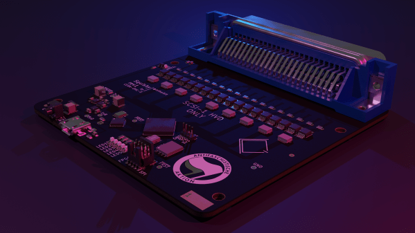
Revive A Sony Vaio P-Series With KiCad’s Background Bitmaps

You might remember that KiCad 7 came out this February, with a multitude of wonderful features. One of them was particularly exciting to see, and the KiCad newsletter even had an animated GIF to properly demo it – a feature called “Background Bitmaps”, which is the ability to add existing board images into your board editor, both front and back, and switch between them as you design the board. With it, you can draw traces, recreate the outline and place connectors over these images, giving you a way to quickly to reproduce everything on an existing PCB! I’ve seen some friends of mine use this feature, and recently, I’ve had a project come up that’s a perfect excuse for me to try it.

By [Yoggy], CC-BY-2.0
Back in 2020, I managed to get a Sony Vaio P from a flea market, for about 20€. It’s a beloved tiny laptop from 2009, now a collectors item, and we’ve covered a few hacks with it! The price was this wonderful only because it was not fit for regular flea market customers – it was in bad condition, with the original DC jack lost and replaced by some Molex-like power connector, no hard drive, and no battery in sight.

In short, something worth selling to a known tinkerer like me, but not particularly interesting otherwise. Nevertheless, about half a year later, when I fed it the desired 10.5 V from a lab PSU and gave the power button a few chances, it eventually booted up and shown me the BIOS menu on the screen! I’ve disassembled and reassembled it a few times, replaced the DC jack with an original one from a different Vaio ultrabook I happened to have parts from, and decided to try to bring it back to original condition.

Continue reading “Revive A Sony Vaio P-Series With KiCad’s Background Bitmaps”

Making A Solder Paste Stencil From What You Have On Hand

Sometimes there are moments when an engineer has to use whatever materials they have to hand in order to complete the job on time. Such a situation arose at the RevSpace hacker space in Den Haag, Netherlands, as they were the assembly venue for a conference badge.

Their problem was that the badge PCB had no solder paste stencil, and the solution was to laser cut one out of an unexpected material. The backing paper for self-adhesive vinyl sheet has properties not unlike those desired of a stencil, so they tried laser-cutting one from that material. The result was a robust stencil that outperformed the Mylar they had previously used, enabled the manufacture of 350 boards.

They think that the polymer layer on top of the paper may be silicone, and found that the laser didn’t unduly melt the edges of the cut. We’re not sure we’d feed random unknown plastics into our cutter, we’re guessing they have good quality ventilation. It’s mounted into a plywood jig in much the same way as a conventional stencil might be.

The badges were destined for WICCON, a Dutch conference from an organisation for women in cybersecurity. Sadly we’ve not seen a completed one so we’re not sure what it does, however we’re pleased to hear they were completed before the event. That’s a hurdle all badge designers will know well.

Long term readers may remember, that RevSpace have something of a history when it comes to assembling badges.

Designing A PCB GPS Antenna From Scratch

These days, when it comes to GPS devices the antenna is typically part of the package. But what better opportunity for [Pepijn] to learn how to make a GPS antenna from scratch for a badge add-on?

A patch antenna is an antenna of a flat design, which [Pepijn] was going to put directly on a PCB. However, there was added complexity due to GPS being a circularly polarized signal, and that meant doing some research.

Sadly, nowhere did [Pepijn] encounter a straightforward reference design or examples, but in the end success came from going with a truncated corner patch antenna design and using simulation software to figure out exactly what dimensions were needed. (The openEMS free simulation software didn’t bring success, but the non-free Sonnet with a trial license did the trick.) The resulting PCB may not look particularly complex, but every detail matters in such designs.

KiCad handled the PCB CAD design but the prototype came from cutting the PCB on a CNC machine instead of having it fabricated and shipped; a much cheaper and faster option for those with access to the right tools. A bit more testing had the prototype looking good, but the real proof came when it successfully received GPS signals and spewed valid NMEA messages. The design files are on GitHub but as [Pepijn] says, the project was about the journey more than anything else.

PCB Repair Is A Sticky Proposition

What do you do when a PCB is cracked or even broken in two? [MH987] has a plan: superglue the board back and then bridge the traces with solder, solder paste, or wire. The exact method, of course, depends on the extent of the damage.

We’ve had some success with similar techniques, and, honestly, for single-sided boards, we would be tempted to add a thin backer behind the crack. We’ve also used conductive paint to repair traces, but it’s good to have having as many tricks as possible because you never know what will work best for a particular repair. The post mentions that this is easier to do on a single-sided board, but it is certainly possible to do on a two-layer board.

The example repair is a Walkman which — if you are a youngster — was a portable music player that takes cassette tapes. These haven’t been made since 2010, so it is important to repair what you have.

If you can’t repair your Walkman, you could build an updated version. If your board is seriously damaged, you might get hope from this more extreme repair.

An In-Depth Comparison Of Hobby PCB Manufacturers

[Icamtuf] has been working on a prototyping run of a project, which involves getting PCBs made by several low volume PCB manufacturing companies. After receiving the boards, he analyzed the results and produced an interesting analysis.

The project he is working on is Sir-Box-A-Lot, a Sokoban gaming console clone that we’ve covered before. It uses an AVR128DA28 microcontroller to emulate the original box-pushing game and drive the OLED display. He ordered PCBs from OSHPark, DigiKey Red, JLCPCB, PCBWay and Aisler.

OSHPark boards are gorgeous, but you pay for it.

There were pros and cons for each of the services: OSHPark produced the nicest-looking boards, but at the highest cost. DigiKey Red had a flawless solder mask, but a rather sloppy-looking silkscreen and shipped the boards covered in adhesive gunk. JLCPCB was fast, shipping the boards in less than 7 days, but the smaller details of the silkscreen were blurry and the solder mask was thinner than the others. The solder mask from PCBWay was very slightly misaligned but was thicker than most, and they were the only ones who queried a badly shaped hole to see what [Icamtuf] wanted to do: the others just made assumptions and made the boards without checking.

To be fair, this analysis is based on a single PCB design ordered once and it is possible that some companies were having a bad day. These were also delivered to the US, so your delivery times may vary. So, there are no clear winners and I wouldn’t make a choice based on this alone. But the analysis is well worth a read if you want to know what to look out for on your own PCBs.

Try It Out

It’s like Star Wars versus Star Trek at a SciFi convention, or asking creamy or chunky at the National Peanut Butter Appreciation Festival. (OK, we made that one up.) When Jenny reviewed the 1.0 version of LibrePCB, it opened the floodgates. Only on Hackaday!

Of course it makes sense that in a community of hardware hackers, folks who are not unfamiliar with the fine art and engineering of designing their own PCBs, have their favorite tools. Let’s face it, all PCB design software is idiosyncratic, and takes some learning. But the more fluent you are with your tool of choice, the more effort you have invested in mastering it, leading to something like the sunk-cost phenomenon: because you’ve put so much into it, you can’t think of leaving it.

The beauty of open-source software tools is that there’s almost nothing, aside from your own psychology, stopping you from picking up another PCB program, kicking the proverbial tires with a simple design, and seeing how it works for you. That’s what Jenny did here, and what she’s encouraged me to do. Whether it’s beginner-friendly Fritzing (also recently in version 1.0), upstarts LibrePCB or Horizon EDA, heavyweight champion KiCAD, or the loose-knit conglomeration of tools in coralEDA, you have enough choices that something is going to fit your PCB hand like a glove.

I certainly wouldn’t risk a swap up to a new tool on something super complicated, or something with a tight deadline, but why not start up a fun project to test it out? Maybe follow Tom Nardi’s lead and make a Simple Add-on, for a badge or just as a blinky to put on your desk? Don’t be afraid to try something new!

Chip Shortage Engineering: Misusing DIP Packages

After years of seeing people showing off and trading their badge Simple Add-Ons (SAOs) at Supercon, this year I finally decided to make one myself. Now for a first attempt, it would have been enough to come up with some cool PCB art and stick a few LEDs on it. But naturally I started with a concept that was far more ambitious than necessary, and before long, had convinced myself that the only way to do the thing justice was to have an onboard microcontroller.

My first thought was to go with the venerable ATtiny85, and since I already had a considerable stock of the classic eight-pin DIP MCUs on hand, that’s what I started prototyping with. After I had something working on the breadboard, the plan was to switch over to the SOIC-8 version of the chip which would be far more appropriate for something as small as an SAO.

Unfortunately, that’s where things got tricky. I quickly found that none of the major players actually had the SMD version of the chip in stock. Both DigiKey and Mouser said they didn’t expect to get more in until early 2024, and while Arrow briefly showed around 3,000 on hand, they were all gone by the time I checked back. But that was only half the problem — even if they had them, $1.50 a piece seems a hell of a lot of money for an 8-bit MCU with 8K of flash in 2023.

The whole thing was made all the more frustrating by the pile of DIP8 ATtiny85s sitting on the bench, mocking me. Under normal circumstances, using them in an SAO wouldn’t really be a problem, but eight hand-soldered leads popping through the front artwork would screw up the look I had in mind.

While brooding over the situation my eyes happened to fall on one of the chips I had been fiddling with, it’s legs badly bent from repeated trips through the programmer. Suddenly it occurred to me that maybe there was a way to use the parts I already had…

Continue reading “Chip Shortage Engineering: Misusing DIP Packages”