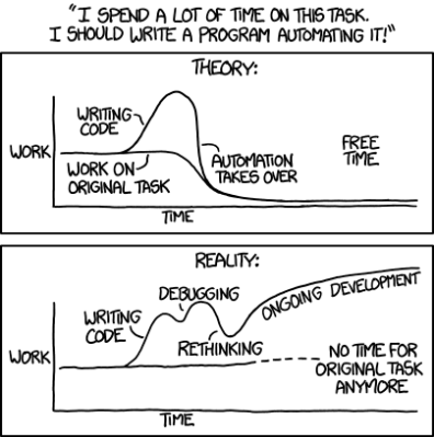
It’s one of the great cliches in the hacker world: the hardware type and the software type. You can tell which of these two you are quite easily. When a project is actually 20% done, but you think it’s 90% done, and you say to yourself “And the rest is a simple matter of software”, you’re a hardware type. Ask anyone who has read my code, and they’ll tell you, I’m a hardware type.
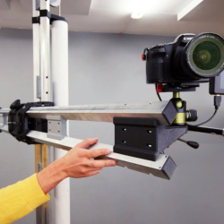
 Along with my blindness to the difficulties of getting the code right, I’ve also admittedly got an underappreciation of what powers lie in the dark typing arts. But I am not too proud to tip my hat when I see an awesome application of the soft stuff. Case in point: this Go board sequencer that we ran last week. An overhead webcam parses players’ moves as they put black and white stones down while playing the game of Go, and turns this into music.
The pure software type will be saying “but there’s a webcam and a Go board”. And indeed, that’s true. There are physical elements to this project that anchor it in the shared reality of the two people playing. But a hardware project this isn’t; it’s OpenCV and Max/MSP that make it work.
 For comparison, look at the complexity of this similar physical sequencer. It’s got a 16 x 16 array of LEDs and switches and a CNC milled, primed, and painted surface that’s the size of a twin bed. Sawdust and hand-soldering: that’s a hardware project.
What I love about the Go sequencer is that it uses software just right. The piece is still physical. It could have just as easily been a VR world, where the two people would interact with each other only inside their goggles. But somehow that’s not quite as human as putting stones on a wooden board, sitting across from, and maybe even looking at, your opponent. The players aren’t forced to think about the software. They don’t feel like they’re playing a video game.
But at the same time, the software side of things makes all of the horrible hardware problems go away. Nobody is soldering a rat’s nest of 169 switches. There’s a webcam plugged into the USB port of a laptop. There’s a deep simplicity there.
Should you always trade out arcade buttons for OpenCV? Absolutely not! But is it worth considering the soft side when doing it in hardware is just too, well, hard? I’m open.


