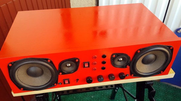
At first glance, this fire engine red speaker box built by [NoshBar] looks straightforward enough. Just an MDF case and couple of drivers recovered from a trashed stereo. But the array of controls and connectors on the front, and a peek on the inside, shows there’s more to this particular project than meets the eye.
 Built almost entirely from parts [NoshBar] found in the trash, construction started with some salvaged MDF IKEA shelves and their corresponding twist lock cam fittings. We don’t usually see those style cam fittings used to build DIY enclosures, but if it works for all those furniture manufacturers why not?
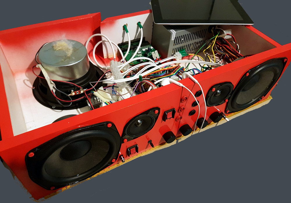
A pair of Sony stereo speakers he found gave up their internals, and a TPA3116 amplifier board off of eBay drives them. He’s wired up an audio pass-through mode for using headphones when the amplifier is powered off, and dual inputs so he can switch between PC and PS4.
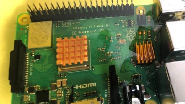
But the audio components are only half of what’s inside that shiny red exterior. [NoshBar] packed in an ATX PSU and broke out the 3.3 V, 5 V, and 12 V lines to the front panel so he can use it as a bench power supply for his Arduino projects. It’s also home to a gigabit Ethernet switch and a Raspberry Pi acting as a file server.
We’re always amazed at what hackers are able to accomplish with parts they’ve literally pulled out of the trash, from a waterwheel to charge your phone to a functional CNC router. It seems there’s plenty of treasure in your local dumpster if you’re willing to get a little dirty.