Who wouldn’t want a robot that can fetch them a glass of water? [Saral Tayal] didn’t just think that, he jumped right in and built his own personal assistant robot. This isn’t just some remote-controlled rover though. The robot actually listens to his voice and recognizes his face.
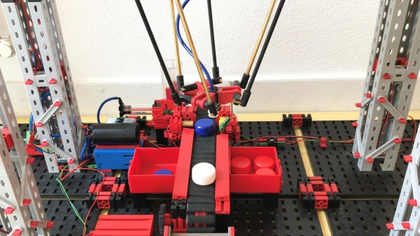
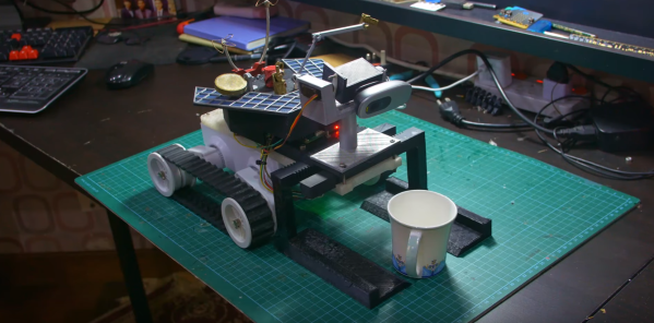
The body of the robot is the common “Rover 5” platform, to which [Saral] added a number of 3D printed parts. A forklift like sled gives the robot the ability to pick things up. Some of the parts are more about form than function – [Saral] loves NASA’s Spirit and Opportunity Mars rovers, so he added some simulated solar cells and other greebles.
The Logitech webcam up front is very functional — images are fed to machine learning models, while audio is processed to listen for commands. This robot can find and pick up 90 unique objects.
The robot’s brains are a Raspberry Pi. It uses TensorFlow for object recognition. Some of the models [Saral] is using are pretty large – so big that the Pi could only manage a couple of frames per second at 100% CPU utilization. A Google Coral coprocessor sped things up quite a bit, while only using about 30% of the Pi’s processor.
It takes several motors to control to robot’s tracks and sled. This is handled by two Roboclaw motor controllers which themselves are commanded by the Pi.
We’ve seen quite a few mobile robot rovers over the years, but [Saral’s] ‘bot is one of the most functional designs out there. Even better is the fact that it is completely open source. You can find the code and 3D models on his GitHub repo.
Check out a video of the personal assistant rover in action after the break.
Continue reading “DIY Personal Assistant Robot Hears And Sees All”