A couple of weeks ago we covered the launch of the Odroid C2, a single board computer from the Korean company Hardkernel in the same form factor and price segment as the Raspberry Pi 3. With four ARM Cortex A53 cores at 2GHz and 2Gb of DDR3 on board it has a paper spec that comfortably exceeds that of the Pi 3’s 1.2GHz take on the same cores and 1Gb of DDR2. This could be a board of great interest to our readers, so we ordered one for review.
The parcel from Korea arrived in due course, the C2 in its box inside it well protected by a sturdy cardboard outer packaging. We had ordered a couple of extras: a micro-SD card preloaded with Ubuntu and a USB power lead (more on that later), both were present and correct.
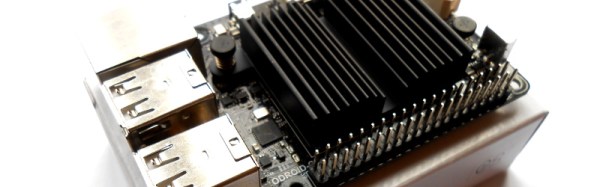
When unpacking the board it is immediately obvious how closely they’ve followed the Raspberry Pi form factor. There are a few differences, no camera or DSI connectors, the SD card in a different place, a power jack where the Pi has its audio jack, and oddly the network port is the other way up. Otherwise it looks as though it should fit most Pi cases. Of course the only case we had to hand was a PiBow which are cut for specific Pi models, so sadly we couldn’t test that assertion.
Continue reading “Hands On With The Odroid C2; The Raspberry Pi 3 Challenger”