Yellow Robot Wheels Rolling Out

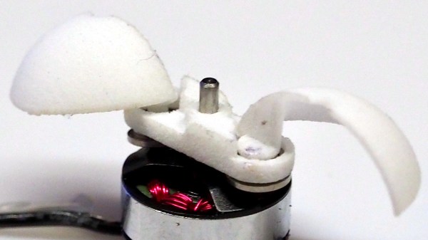
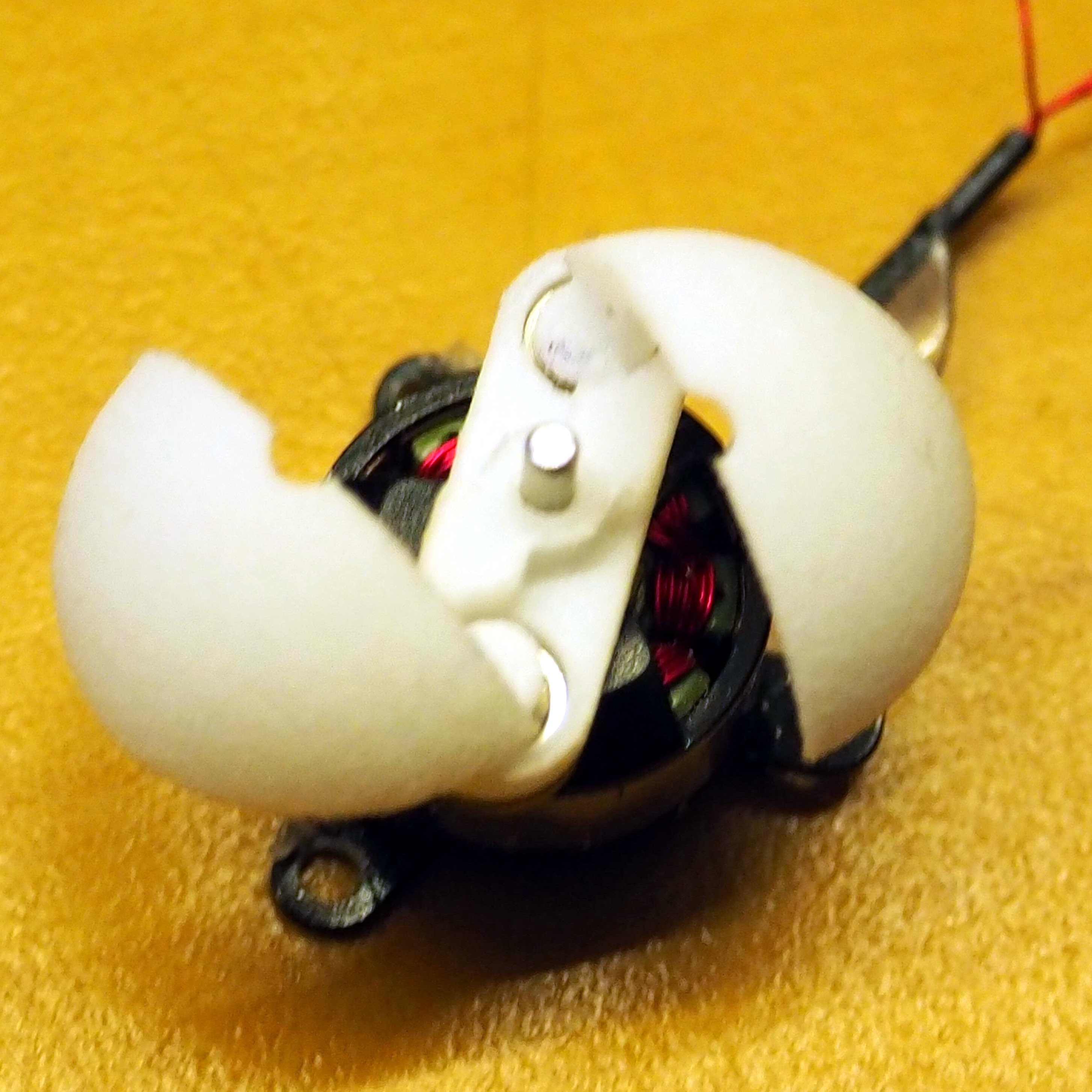
Small wheeled robots are great for exploring robotics and it’s easier than ever to get started, thanks to growing availability and affordability of basic components. One such component is a small motorized wheel assembly commonly shown when searching for “robot wheel”: a small DC motor mounted in a gearbox to drive a single plastic wheel (inevitably yellow) on which a thin rubber tire has been mounted for traction. Many projects have employed these little motor + gearbox + wheel modules, such as these three entries for 2018 Hackaday Prize:

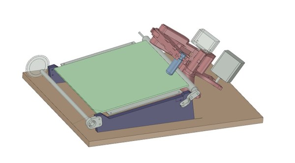
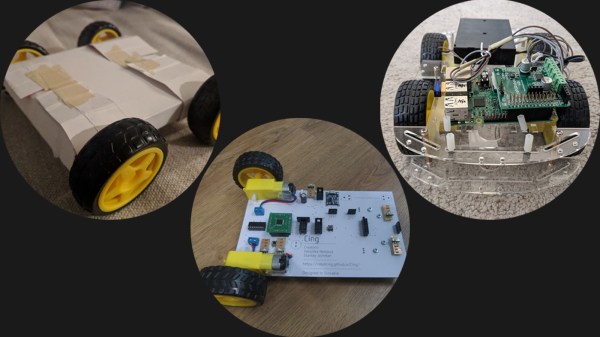
BoxBotics takes the idea of an affordable entry point and runs with it: build robot chassis for these wheels out of cardboard boxes. (Maybe even the exact box that shipped the yellow wheels.) Cardboard is cheap and easy to work with, making cardboard projects approachable to any creative mind. There will be an audience for something like a Nintendo Labo for robotics, and maybe BoxBotics will grow into that offering.

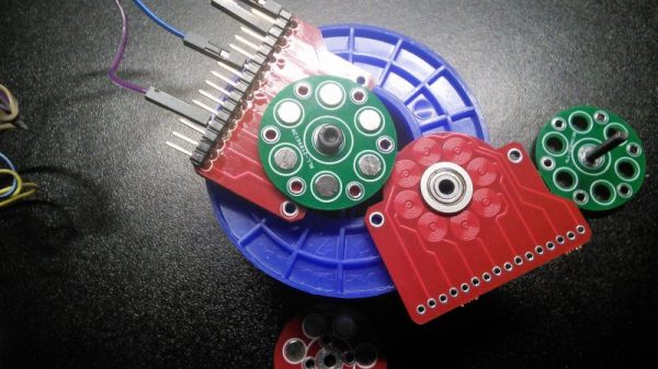
Cing also intends to make a friendly entry point for robotics and they offer a different chassis solution. Instead of cardboard, they use a circuit board. The yellow gearbox is mounted directly to the main circuit board making it into the physical spine, along with its copper traces serving as the spinal cord of the robot. While less amenable to mechanical creativity than BoxBotics, Cing’s swappable modules might be a better fit for those interested in exploring electronics.

ROS Starter Robot caters to those who wish to go far beyond simple “make it move” level of robot intelligence. It aims to lower the barrier to enter the world of ROS (robot operating system) which has historically been the domain of very capable (but also very expensive) research-oriented robots. This project could become the bridge for aspiring roboticists who wish to grow beyond hobbyist level software but can’t justify the cost typical of research level hardware.

All three of these projects take the same simple motorized wheel and build very different ideas on top of them. This is exactly the diversity of ideas we want to motivate with the Hackaday Prize and we hope to see great progress on all prize contestants in the month ahead.

Thermoelectric Generator Shines Where The Sun Doesn’t

For off-grid renewable electricity, solar seems to make sense. Just throw some PV panels on the roof and you’re all set to stick it to the man, right? But the dirty little secret of the king of clean energy is that very few places on the planet get the sort of sunshine needed to make residential PV panels worth their installation cost in the short term, and the long-term value proposition isn’t very good either.

The drearier places on the planet might benefit from this high-power thermoelectric generator (TEG) developed and tested by [TegwynTwmffat] for use on a wood burning stove. The TEG modules [Tegwyn] used are commercially available and rated at 14.4 volts and 20 watts each. He wisely started his experiments with a single module; the video below shows the development of that prototype. The bulk of the work with TEGs is keeping the cold side of the module at a low enough temperature for decent performance, since the modules work better the higher the difference in temperature is across the module. A finned heatsink and a fan wouldn’t cut it for this application, so a water-cooled block was built to pump away the heat. A successful test led to scaling the generator up to 10 modules with a very impressive heatsink, which produced about 120 watts. Pretty good, but we wonder if some easy gains in performance would have come from using heat sink compound on the module surfaces.

Using thermal differences to generate electricity is nothing new, but a twist on the technique is getting attention lately as a potential clean energy source. And who knows? Maybe [TegwynTwmffat]’s or one of the other Hackaday Prize 2018 entries will break new ground and change the world. What’s your big idea?

Continue reading “Thermoelectric Generator Shines Where The Sun Doesn’t”

Watch This Tiny Dome Auto-open And Close Into A Propeller

Careful planning and simulation is invaluable, but it can also be rewarding to dive directly into prototyping. This is the approach [Carl Bugeja] took with his Spherical Folding Propeller design which he has entered into the Open Hardware Design Challenge category of The 2018 Hackaday Prize. While at rest, the folding propeller looks like a small dome attached to the top of a motor. As the motor fires up, centrifugal forces cause the two main halves of the dome to unfold outward where they act as propeller blades. When the motor stops, the assembly snaps shut again.

[Carl] has done some initial tests with his first prototype attached to a digital scale as a way of measuring thrust. The test unit isn’t large — the dome is only 1.6 cm in diameter when folded — but he feels the results are promising considering the small size of the props and the fact that no simulation work was done during the initial design. [Carl] is looking to optimize the actual thrust that can be delivered, now that it has been shown that his idea of a folding dome works as imagined.

Going straight to physical prototyping with an idea can be a valid approach to early development, especially nowadays when high quality components and technologies are easily available even to hobbyists. Plus it can be great fun! You can see and hear [Carl]’s prototype in the short video embedded below.

Continue reading “Watch This Tiny Dome Auto-open And Close Into A Propeller”

A High Speed, Infinite Volume 3D Printer

One of the most interesting developments in 3D printing in recent memory is the infinite build volume printer. Instead of a static bed, this type of printer uses a conveyor belt and a hotend set at an angle to produce parts that can be infinitely long in one axis, provided you have the plastic and electricity. For this year’s Hackaday Prize, [inven2main] is exploring the infinite build volume design, but putting a new spin on it. This is a printer with a conveyor belt and a SCARA arm. The goal of this project is to build a printer with a small footprint, huge build volume, no expensive rails or frames, and a low part count. It is the most capable 3D printer you can imagine using a minimal amount of parts.

Most of the documentation for this build is hanging around on the RepRap forums, but the bulk of the work is already done. The first half of this build — the SCARA arm — is well-traveled territory for the RepRap community, and where there’s some fancy math and kinematics going on, there’s nothing too far out of the ordinary. The real trick here is combining a SCARA arm with a conveyor belt to give the project an infinite build volume. The proof of concept works, using a conveyor belt manufactured out of blue painter’s tape. These conveyor belt printers are new, and the bed technology isn’t quite there, but improvements are sure to come. Improvements will also be found in putting a small crown on the rollers to keep the belt centered.

All the files for this printer are available on the Gits, and there are already a few videos of this printer working. You can check those out here.

A Brushless Motor On A PCB, Made From PCB

At Hackaday, we really appreciate it when new projects build on projects we’ve featured in the past. It’s great to be able to track back and see what inspires people to pick up someone else’s work and bring it to the next level or take it down a totally new path.

This PCB brushless motor is a great example of the soft collaboration that makes the Hackaday community so powerful. [bobricius] says he was inspired by this tiny PCB BLDC when he came up with his design. His write-up is still sparse at this point, but it looks like his motor is going to be used to drive a small robot. As with his inspiration, this motor has the stator coils etched right into the base PCB. But there are some significant improvements, like increasing the stator coil count from six to eight, as well as increasing the overall size of the motor. [bobricius] has also done away with the 3D-printed rotor of the original, opting to fabricate his rotor from stacked PCBs with cutouts for 5-mm neodymium magnets. We like the idea of using the same material throughout the motor, and it also raises the potential for stacking a second stator on the other side of the rotor, which might help mechanically and electrically. Even still, the prototype seems to hold its own in the video below.

This is [bobricius]’ second entry in the 2018 Hackaday Prize so far, after his not-a-Nixie tube display. Have you entered anything yet? Get to it! Prizes, achievements, and glory await.

Continue reading “A Brushless Motor On A PCB, Made From PCB”

Neon Display For A Vacuum Tube Calculator

When it comes to vintage displays, everyone gravitates to Nixies. These tubes look great, but you’re dealing with a certain aesthetic with these vintage numeric tubes. There is another option. For his Hackaday Prize entry, [castvee8] is making seven-segment displays out of vintage neon lamps. It looks great, and it’s the basis of an all-vacuum tube calculator.

The core of this build are a few tiny NE-2 neon bulbs. These are the same type of bulbs you’ll find in old indicators, and require somewhere around 100 volts to fire. These bulbs are then installed in a 3D-printed frame, giving [castvee] a real seven-segment display, a plus or minus sign, and an equals sign. It’s the beginnings of a calculator, right there.

One of the recent updates to this project is controlling these displays with modern logic. That might be a bit of a misnomer, because [castvee] is using diode steering and a TTL chip to cycle through the numbers 1 to 4. The actual code to do this is running on a microcontroller, though, so that might get a pass. This is just a test, though, and the real project looks to be an all-vacuum calculator. The project is still in its early stages, but there are still months to go in the Hackaday Prize, and we can’t wait to see what comes out of this project.

It’s A Nixie! It’s A VFD! No, It’s A Custom LED Display In A Tube

Like the look of Nixies but they just seem a little overdone? Or perhaps you just don’t want the hassles of a high-voltage power supply? Then maybe these faux-Nixie LED “tube” displays will find a way into your next clock build.

For his 2018 Hackaday Prize entry, [bobricius] decided that what the world needs is a Nixie that’s not a Nixie. To that end, each display is formed by seven surface-mount LEDs soldered to a seven-segment shaped PCB and slipped into a glass tube. The LEDs are in 4014 packages so they’re only 4 millimeters long, but what they lack in size they make up for in brightness. We’re not sure if it’s a trick of the camera, but the LEDs certainly seem to put off a bluish glow that’s reminiscent of vacuum-fluorescent displays — it’s like a Nixie and a VFD all rolled up in one package.  The current case, which hides the clock circuitry on the lower part of the PCB, is just plastic, but this would look spiffy in a fine wooden case.

Could this be another Nixie tube killer that never was? Perhaps, but wherever it ends up, we like the look of it, and we’re glad it’s one of the early Hackaday Prize entries. Have you got something to enter in the greatest hardware competition on Earth? If not, get cracking!