From reading his extensive write-ups on the subject, there’s one thing we know for sure: [Tom Verbeure] loves his Tektronix TDS 420A oscilloscope. While it might be older than some of the people reading this, it’s still an impressive piece of hardware with more than enough bells and whistles to keep the average hacker occupied. Especially if you’re willing to perform some hardware modifications.
[Tom] already knew how to tickle the scope into unlocking software features, a process not unlike what we’ve seen done on more modern scopes. But there’s only so far you can get by toggling software flags.
Some of the more advanced features that are turned off in the firmware actually need additional hardware to function. Simply bumping the sample points to 120,000 in software wasn’t enough, the scope actually needs the memory to hold them in.
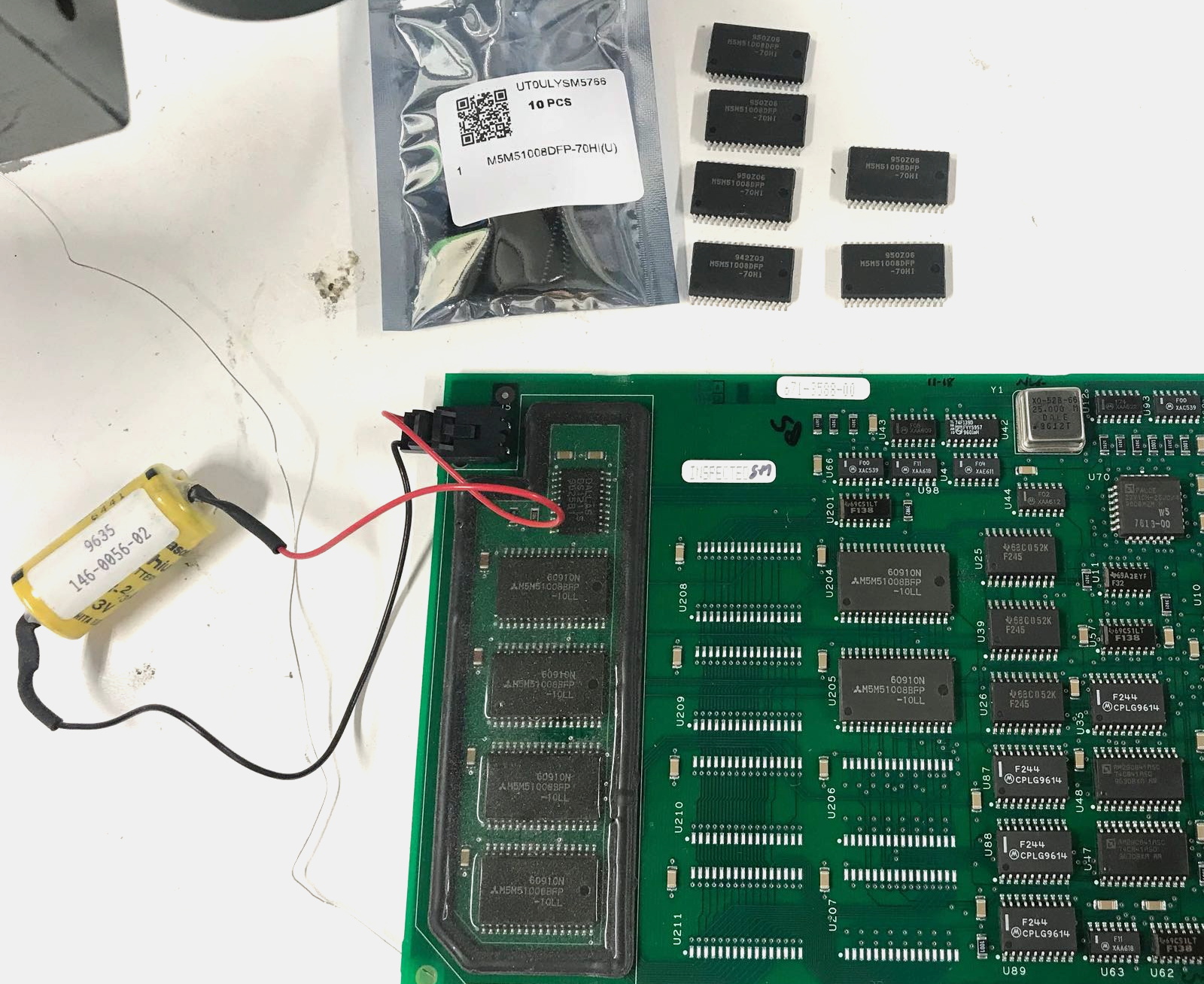
Now logically, if there’s a software option to increase the number of samples, there must be a hardware upgrade that goes along with it. Sure enough, [Tom] found there were 6 open spots next to the scope’s existing M5M51008 static RAM ICs.
As luck would have it the chips are still available, albeit from a different manufacturer and a bit faster than the original parts. Digikey wouldn’t sell fewer than 100 of them, but UTSource was happy to sell him 10. In this case, the parts were cheaper than the shipping cost. Installation was about as straightforward as it gets, though [Tom] does note that he had to keep the board powered up during the operation or else the scope would have lost its calibration data.
Squeezing more features out of modern scopes like the Rigol DS2072A just takes a USB cable and some software. Sometimes it’s only a matter of tapping in a code. But we certainly appreciate [Tom] putting in a little extra effort to get the most out of this classic piece of hardware.