If you want to hack around with the communication protocol that USB Power Delivery devices use to negotiate their power requirements with the upstream source, a tool like Google’s Twinkie really helps. With it you can sniff data off the line, analyze it, and even inject your own packets. Luckily for us, the search giant made the device open source so we can all have one of our own.
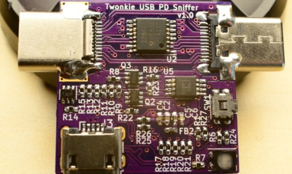
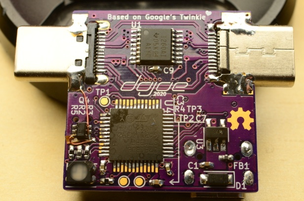
Unfortunately, as [dojoe] found out, the Twinkie isn’t particularly well suited for small-scale hobbyist manufacturing. So he came up with a revised design he calls Twonkie that replaces the six layer PCB with a much more reasonable four layer version that can be manufactured cheaply by OSHPark, and swaps out the BGA components with QFP alternatives you can hand solder.
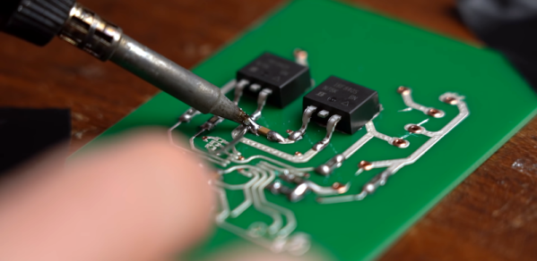
 That said, it’s still likely to be a challenging build for the home gamer. There’s quite a few 0402 passives on there, and while those are doable with an iron, it can certainly be tricky. To take some pressure off, [dojoe] says he tried to optimize the board layout as much as possible for hand assembly. He was even able to avoid needing hot air by straddling the PCB with USB-C mounts intended for vertical applications.
Given the current chip shortage, [dojoe] says the biggest problem might actually getting your hands on the STM32F072CB microcontroller at the Twonkie’s core. To that end, the board supports TQFP44 and QFN44 footprints, and you can even use a STM32F072C8 at the cost of some functionality. With a bit of luck, hopefully you can find a chip that will work in the parts bin.
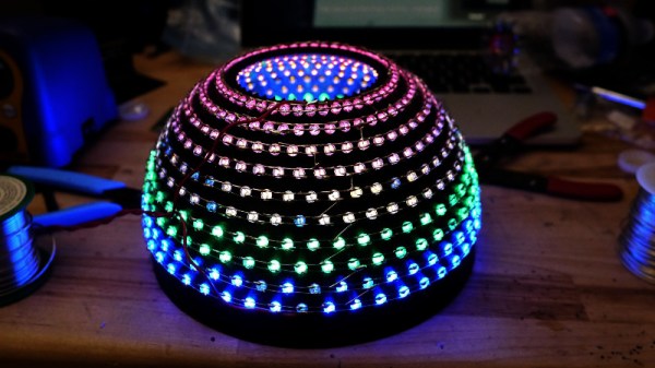
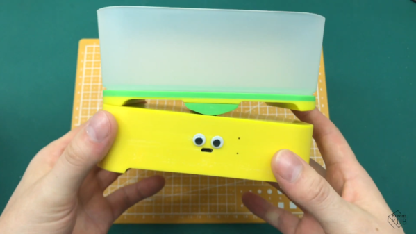
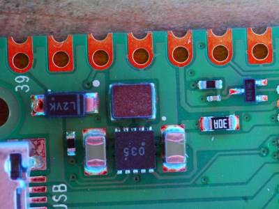 The principle behind this tool is as unexpected and simple as it is clever; by having different colours of light from different elevations of the dome it ensures that each different angle of the solder joint surface reflects a different colour. Thus a colour photograph shot from directly above the board allows visual inspection of the quality of the solder joints by the rainbow of colours that appears around their edges. This process can even be automated with OpenCV or similar, hence the process is referred to as Automated Optical Inspection, or AOI.