It probably goes without saying that we’d all love to have a huge, well-appointed, workshop. But in reality, most of us have to make do with considerably less. When trying to fit tools and equipment into a small space you need to get creative, and if you can figure out a way to squeeze multiple functions out of something, all the better.
Wanting to get as much use out of his space as possible, [Chris Chimienti] decided that his best bet would be to design and build his own folding combination table. Using interchangeable inserts it can switch between being a table saw and a router, and with its extendable arms, also serves as a stand for his miter saw. Of course when not cutting, it makes a handy general purpose work surface.
 In the videos after the break, [Chris] takes viewers through the design and construction of what he calls the “Sinister Saw”, which is made somewhat more complicated by the fact that he obviously doesn’t have a table saw to begin with. Cutting out the pieces for the table itself and the panels that would eventually become home to the router and circular saw took some careful work with clamps and saw horses to make sure they were all perfectly square.
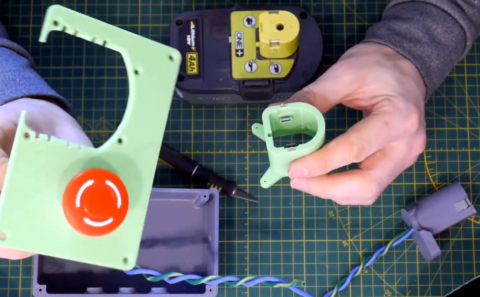
But the wooden components of the Sinister Saw are only half of the story. The table is able to extend by way of an aluminum extrusion frame, and there are numerous 3D printed parts involved for which [Chris] has provided the STL files. We particularly like the box that holds the emergency stop button and relocates the tool’s battery to the front panel, which looks to be an evolution of his previous work in 3D printing cordless tool adapters. We could certainly see this part being useful on other projects that utilize these style of batteries.
In the other extreme, where you want to build your own tools and have plenty of space, you could try making everything out of giant slabs of stone.
Continue reading “A Custom Saw Designed For Close Quarters Making”