For switching high-powered loads from a microcontroller, or for switching AC loads in general, most of us will reach into the parts bin and pull out a generic relay of some sort. Relays are fundamental, proven technologies to safely switch all kinds of loads. They do have their downsides, though, so if you need silent operation, precise timing, or the ability to operate orders of magnitude more times you might want to look at a triac instead. These solid state devices can switch AC loads unlike other transistor-based devices and [Ray] at OpenSprinkler is here to give us an overview on how to use them.
The key to switching an AC load is bi-directional conductivity. A normal transistor or diode can only conduct in one direction, so if you try to switch an AC load with one of these you’ll end up with what essentially amounts to a bad rectifier. Triacs do have a “gate” analogous to the base of a bipolar junction transistor, but the gate will trigger the triac when current flows in either direction as well. The amount of current needed to trigger the triac does depend on the state of the switched waveform, so it can be more complex to configure than a relay or transistor in some situations.
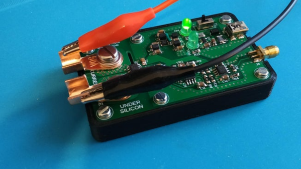
After going through some of the theory around these devices, [Ray] demonstrates how to use them with an irrigation system, which are almost always operating on a 24VAC system thanks to various historical quirks. This involves providing the triacs with a low voltage source to provide gate current as well as a few other steps. But with that out of the way, switching AC loads with triacs can become second nature. If you prefer a DC setup for your sprinklers, though, [vinthewrench] has demonstrated how to convert these sprinkler systems instead.


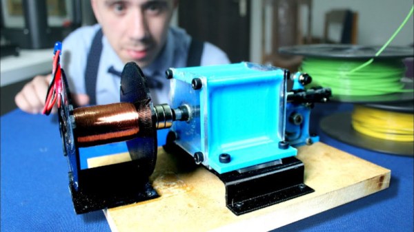

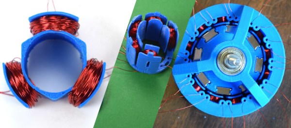
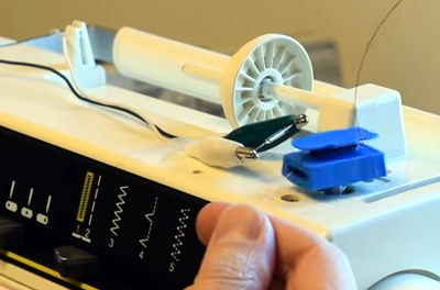 The fun of this project is copying the components found in the commercial hardware and varying the windings and coil count to see how it affects performance. If you have ever wound magnet wire around a nail to make an electromagnet, you know it is tedious work so check out their 3D printed coil holder with an embedded magnet to trigger a winding count and a socket to fit on a sewing machine bobbin winder. If you are going to make a bunch of coils, this is going to save headaches and wrist tendons.