Line Followers are a tried-and-true type of robot; both hardware and software need to be doing their job in harmony in order to be successful at a clearly defined physical task. But robots don’t always have microcontrollers and software, as [Mati_DIY]’s zero programming analog line follower demonstrates.
For readers used to seeing a Raspberry Pi or Arduino in almost everything, an analog robot whose “programming” exists only as a harmony between its discrete parts can be an eye-opener as well as an accessible project. A video of the robot in action is embedded below.
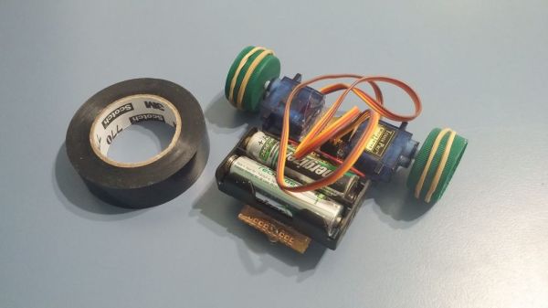
[Mati_DIY]’s design uses two CNY70 reflective sensors (which are essentially infrared emitter/phototransistor pairs) and an LM358 dual op-amp. Together, the sensors act as two near-sighted eyes. By using the output of each sensor to drive a motor via a transistor, the presence or absence of the black line is directly and immediately reflected by the motion of the attached motor. The more black the sensor sees, the more the motor turns. Electrically, that’s all that happens; but by attaching the right sensor to the left motor and the left sensor to the right motor, you get a robot that always tries to keep the black line centered under the sensors. Playing with the spacing of the motors and sensors further tweaks the performance.
Continue reading “Line Follower Has Lots Of Recycled Parts, But Zero Brains”