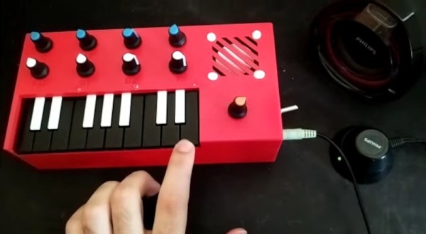
IR Remote tester in use, showing a remote control lighting up an LED and screenshots of the Arduino serial terminal

IR Remote Tester Helps You Crack The Code

Even though some devices now use WiFi and Bluetooth, so much of our home entertainment equipment still relies on its own proprietary infrared remote control. By and large (when you can find them) they work fine, but what happens when they stop working?  First port of call is to change the batteries, of course, but once you’ve tried that what do you do next? [Hulk] has your back with this simple but effective IR Remote Tester / Decoder.

IR remote tester schematic showing arduino, receiver, LED and resistor
How to connect the TSOP4838 to an Arduino to read the transmitted codes

By using a cheap integrated IR receiver/decoder device (the venerable TSOP4838), most of the hard work is done for you! For a quick visual check that your remote is sending codes, it can easily drive a visible LED with just a resistor for a current-limit, and a capacitor to make the flickering easier to see.

For an encore, [Hulk] shows how to connect this up to an Arduino and how to use the “IRremote” library to see the actual data being transmitted when the buttons are pressed.

It’s not much of a leap to imagine what else you might be able to do with this information once you’ve received it – controlling your own projects, cloning the IR remote codes, automating remote control sequences etc..

It’s a great way to make the invisible visible and add some helpful debug information into the mix.

We recently covered a more complex IR cloner, and if you need  to put together a truly universal remote control, then this project may be just what you need.

Continue reading “IR Remote Tester Helps You Crack The Code”

Mini Ultrasonic Levitation Kit Is An Exercise In Sound Minimalist Design

For those that haven’t heard, ultrasonic levitation is a process by which two or more ultrasonic transducers are set opposite to each other and excited in such a way as to create a standing wave between them. The sound is, as the name implies, ultrasonic — so outside the range of human hearing — but strong enough so that the small, light objects can be positioned and held fixed in mid-air where there’s a pressure minimum in the standing wave. [Olimex] has created a small ultrasonic levitation kit that exemplifies this phenomena.

The kit itself is made using through-hole components, with an ATTiny85 as the core microcontroller to drive two TCT40-16T ultrasonic speakers, and a MAX232 to provide a USB interface drives the transducers (thanks to the folks in the comments for the correction). Two slotted rectangular PCB pieces that solder connect to the main board, provide a base so that the device stands upright when assembled. The whole device is powered through the USB connection, and the ultrasonic speakers output in the 40KHz range providing enough power to levitate small Styrofoam balls.

The project is, by design, an exercise in minimalism, providing a kit that can be easily assembled, and providing code that can be easily flashed onto the device, examined and modified. All the design files, including the bill of materials, KiCAD schematics, and source code are provided under an open source hardware license to allow for anyone wanting to know how such a project works, or to extend it themselves, ample opportunity. [Olimex] also has the kit for sale for those not wanting to source boards and parts themselves.

We’ve featured ultrasonic levitation devices before, from bare bones system driven by a NE555 to massive phased arrays.

"The Great Resistor" color code illumination project

The Great Resistor Embiggens The Smallest Value

With surface-mount components quickly becoming the norm, even for homebrew hardware, the resistor color-code can sometimes feel a bit old-hat. However, anybody who has ever tried to identify a random through-hole resistor from a pile of assorted values will know that it’s still a handy skill to have up your sleeve. With this in mind, [j] decided to super-size the color-code with “The Great Resistor”.

Resistor color code from Wikipedia with white background
How the resistor color-code bands work

At the heart of the project is an Arduino Nano clone and a potential divider that measures the resistance of the test resistor against a known fixed value. Using the 16-bit ADC, the range of measurable values is theoretically 0 Ω to 15 MΩ, but there are some remaining issues with electrical noise that currently limit the practical range to between 100 Ω and 2 MΩ.

[j] is measuring the supply voltage to help counteract the noise, but intends to move to an oversampling/averaging method to improve the results in the next iteration.

The measured value is shown on the OLED display at the front, and in resistor color-code on an enormous symbolic resistor lit by WS2812 RGB LEDs behind.

Inside view of the great resistor showing WS2812 LEDs and baffle plates
Inside The Great Resistor, the LEDs and baffle plates make the magic work

Precision aside, the project looks very impressive and we like the way the giant resistor has been constructed. It would look great at a science show or a demonstration. We’re sure that the noise issues can be ironed out, and we’d encourage any readers with experience in this area to offer [j] some tips in the comments below. There’s a video after the break of The Great Resistor being put through its paces!

If you want to know more about the history of the resistor color code bands, then we have you covered.  Alternatively, how about reading the color code directly with computer vision?

Continue reading “The Great Resistor Embiggens The Smallest Value”

The Seven-Segment Display That’s Also An Input Device

We’re used to seeing all manner of seven-segment displays, be they mechanical, electronic, or something in between. But what all these displays have in common is that they’re, you know, displays. Using them as inputs would just be crazy talk, right?

Perhaps, but we like where [Dave Ehnebuske] is going with “InSlide,” the seven-segment input device. The idea for this comes from the “DigiTag” display, which we covered back in October, and divides a standard seven-segment character into three vertical strips — two skinny ones for the outside vertical segments, and one wide strip holding the horizontal elements. By sliding these strips up and down relative to each other, the standard nine digits, plus a few other characters, can be composed.

[Dave]’s take on this theme started by building his display from laser-cut plywood pieces, which is a nice choice because of the good contrast between the white wood and the engraver segments. Next, he embedded rare earth magnets in the slides and installed seven Hall effect sensors in the frame. The sensors are connected to an Arduino Nano via a 74HC165 parallel-load shift register, which lets multiple modules be daisy-chained together. He also built an Arduino library to read the current state of the segments; it supports the full hexadecimal character set, or even duodecimal if you like.

[Dave] has shared the library, and it looks like you can get the build files for the mechanism from the original project. That’s good, because this looks ripe for hacking. It looks like it would be pretty easy to motorize a display like this by adding rack-and-pinion gearing and steppers — something like that could make an interesting clock.

Walnut Case Sets This Custom Arduino-Powered RPN Calculator Apart From The Crowd

How many of us have an everyday tool that’s truly unique? Likely not many of us; take a look around your desk and turn out your pockets, but more often than not, what you’ll find is that everything you have is something that pretty much everyone else on the planet could have bought too. But not so if you’ve got this beautiful custom RPN calculator in a wooden case.

This one comes to us from [Shinsaku Hiura], who generally dazzles us with unique mechanical clocks and displays. This calculator solves a more practical problem — the dearth of RPN calculators on the market with the correct keyboard feel, specifically with the large keys and light touch he desired. Appropriately, the build started with a numeric keypad, which once liberated of its USB interface was reverse-engineered to figure out how the matrix was wired. Next up, a custom PCB to connect the keypad to an Arduino and a 20×4 LCD display was milled up, while a test case was designed and printed to check fitment. The final case was milled from a block of solid walnut and fitted with an acrylic window, for a sharp look with clean lines and pleasing colors.

As for the calculator itself, the demo below shows it going through its paces. The code is clever because it leverages the minimal number of keys available by hiding all the scientific and engineering functions behind a “secret silver key” that was once the equals key and obviously not needed in RPN. Hats off to [Shinsaku] for a handsome and unique addition to his desk.

Continue reading “Walnut Case Sets This Custom Arduino-Powered RPN Calculator Apart From The Crowd”

Gesture Controlled Filming Gear Works Super Intuitively

Shooting good video can be an arduous task if you’re working all by yourself. [Pave Workshop] developed a series of gesture-responsive tools to help out, with a focus on creating a simple intuitive interface.

The system is based around using a Kinect V2 to perceive gestures made by the user, which can then control various objects in the scene. For instance, a beckoning motion can instruct a camera slider to dolly forward or backwards, and a halting gesture will tell it to stop. Bringing the two hands together or apart in special gestures indicate that the camera should zoom in or out. Lights can also be controlled by pulling a fist towards or away from them to change their brightness.

The devil is in the details with a project that works this smoothly. [Pave Workshop] lays out the details on how everything Node.JS was used to knit together everything from the custom camera slider to Philips Hue bulbs and other Arduino components.

The project looks really impressive in the demo video on YouTube. We’ve seen some other impressive automated filming rigs before, too.

Continue reading “Gesture Controlled Filming Gear Works Super Intuitively”

One Of The Worst Keyboards Ever, Now An Arduino Peripheral

For British kids of a certain age, their first experience of a computer was very likely to have been in front of a Sinclair ZX81. The lesser-known predecessor to the wildly-successful ZX Spectrum, it came in at under £100 and sported a Z80 processor and a whopping 1k of memory. In the long tradition of Sinclair products it had a few compromises to achieve that price point, the most obvious of which was a 40-key membrane keyboard. Those who learned to code on its frustrating lack of tactile feedback may be surprised to see an Arduino project presenting it as the perfect way to easily hook up a keyboard to an Arduino.

Like many retrocomputing parts, the ZX81 ‘board has been re-manufactured, to the joy of many a Sinclair enthusiast. It’s thus readily available and relatively cheap (we think they can be found for less than the stated 20 euros!), so surprisingly it’s a reasonable choice for an Arduino project. The task of trying to define by touch the imperceptible difference in thickness of a ZX81 key will bring a true retrocomputing experience to a new generation. Perhaps if it can be done on an Mbed then someone might even make a ZX81 emulator on the Arduino.

We’re great fans of the ZX81 here at Hackaday, for some of us it was that first computer. Long may it continue to delight its fans!