[Bisqwit] has feelings about games that use exclamation points in his idiosyncratic walkthrough of all the nuances of the passwords in the famous Punch Out Bang Bang.
As he states in his deeply weird (though in no way wrong) channel intro, when he’s not driving a bus or teaching Israeli dance, he works hard to understand the things around him. Naturally, a mysterious phone number shaped set of digits in a favorite game was a secret worth extracting.
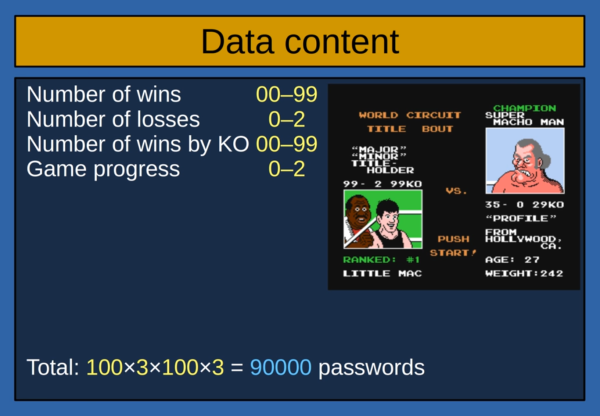
The digits can represent every possible state in the game. It uses a pretty simple decoding and encoding scheme, which he walks through. As he says, it all becomes clear when you can see the source code.
After working through all the quirks he is able to arbitrarily generate any state in the game and handle the exceptions (such as Nintendo USA’s phone number). You can see all his code here and try it out for yourself. Video after the break.
We’ve grown to respect [Bisqwit] as the explainer of all things console games. You will like his explanation of how to write a code emulator for an NES CPU.
Continue reading “Crack Mike Tyson’s Punch Out Bang Bang Passwords”