Coffee Alarm

Alarm Notifies The Office When The Coffee Is Ready

[Stian] thought it would be nice if his coworkers could be electronically notified when the latest batch of coffee is ready. He ended up building an inexpensive coffee alarm system to do exactly that. When the coffee is done, the brewer can press a giant button to notify the rest of the office that it’s time for a cuppa joe.

[Stian’s] first project requirement was to activate the system using a big physical button. He chose a button from Sparkfun, although he ended up modifying it to better suit his needs. The original button came with a single LED built-in. This wasn’t enough for [Stian], so he added two more LEDs. All three LEDs are driven by a ULN2003A NPN transistor array. Now he can flash them in sequence to make a simple animation.

This momentary push button supplies power to a ESP8266 microcontroller using a soft latch power switch. When the momentary switch is pressed, it supplies power to the latch. The latch then powers up the main circuit and continues supplying power even when the push button is released. The reason for this power trickery is to conserve power from the 18650 li-on battery.

The core functionality of the alarm uses a combination of physical hardware and two cloud-based services. The ESP8266 was chosen because it includes a built-in WiFi chip and it only costs five dollars. The microcontroller is configured to connect to the WiFi network with the push of a button. The device also monitors the giant alarm button.

When the button is pressed, it sends an HTTP request to a custom clojure app running on a cloud service called Heroku. The clojure app then stores brewing information in a database and sends a notification to the Slack cloud service. Slack is a sort of project management app that allows multiple users to work on projects and communicate easier over the internet. [Stian] has tapped into it in order to send the actual text notification to his coworkers to let them know that the coffee is ready. Be sure to watch the demo video below. Continue reading “Alarm Notifies The Office When The Coffee Is Ready”


Meter Backlight

Adding A Backlight To A Cheap Multimeter

We don’t all need super high quality electronic testing gear. Sometimes second-hand or inexpensive equipment is accurate enough to get the job done. Though it can be a bit annoying to miss out on some of those “luxury” features. [Ekriirke] had this problem with his cheap multimeter. He wished the LCD screen had a backlight for easier visibility, so rather than upgrade to a more expensive unit he just added one himself.

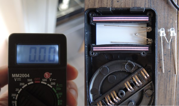
After opening up the multimeter [Ekriirke] found that it ran on a single 12V battery. He realized that the simplest thing to do would be to wire up four white LEDs in series. The four LEDs were arranged within the case off to each side of the LCD, one in each corner. The leads were bent at 90 degree angles and soldered together “dead bug” style. Thin strips of copper foil tape were attached to the PCB in such a way that the anode and cathode from the LEDs would make contact when the case was closed back up.

The tape wraps around to the other side of the PCB where there was more room for the next piece of the circuit. A capacitor, resistor, and transistor are used in conjunction with a momentary switch. This circuit allows [Ekriirke] to turn on the light for about ten seconds by pressing the button one time. The circuit also runs through the meter’s dial switch, preventing the LEDs from being turned on while the meter itself is turned off.

[via Reddit]

Dial

Dial Is A Simple And Effective Wireless Media Controller

[Patrick] was looking for an easier way to control music and movies on his computer from across the room. There is a huge amount of remote control products that could be purchased to do this, but as a hacker [Patrick] wanted to make something himself. He calls his creation, “Dial” and it’s a simple but elegant solution to the problem.

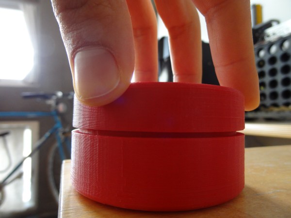
Dial looks like a small cylindrical container that sits on a flat surface. It’s actually split into a top and bottom cylinder. The bottom acts as a base and stays stationary while the top acts as a dial and a push button. The case was designed in SOLIDWORKS and printed on a 3D printer.

The Dial runs on an Arduino Pro mini with a Bluetooth module. The original prototype used Bluetooth 2.0 and required a recharge after about a day. The latest version uses the Bluetooth low energy spec and can reportedly last several weeks on a single charge. Once the LiPo battery dies, it can be recharged easily once plugged into a USB port.

The mechanical component of the dial is actually an off-the-shelf rotary encoder. The encoder included a built-in push button to make things easier. The firmware is able to detect rotation in either direction, a button press, a double press, and a press-and-hold. This gives five different possible functions.

[Patrick] wrote two pieces of software to handle interaction with the Dial. The first is a C program to deal with the Bluetooth communication. The second is actually a set of Apple scripts to actually handle interaction between the Dial and the various media programs on his computer. This allows the user to more easily write their own scripts for whatever software they want. While this may have read like a product review, the Dial is actually open source! Continue reading “Dial Is A Simple And Effective Wireless Media Controller”

Garage Clicker Dashboard Integration

garagedoor-opener-in-dash

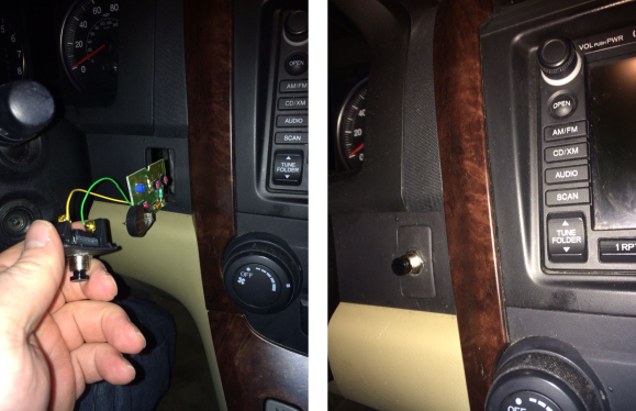
Vehicles with the highest level of trim package sometimes come with the ability to learn garage door opener codes. Less costly offerings lack that feature as well as others bells and whistles, leaving blank plates where fancy buttons would have been. [JiggMcFigg] makes the best of this situation by gutting his garage remote and hiding it behind a button blank.

One thing that raised an eyebrow is the coin cell battery holder you can make out on the size-check image shown to the left. But really, these remotes must drain their batteries at a rate nearly the same as an unused battery so why complicate the hack? A holder was soldered onto the board, and jumper wires were soldered to the push button added to the blank plate. This type of utilitarian button is much more satisfying to use than those fancy-pants silk-screen molded-plastic types anyway!

Of course you could go the other way with this hack. [JiggMcFigg] started out with the problem of losing the remotes in the mess of the car. You could retrofit it with a huge button to make it harder to misplace.

Hackaday Links: October 13, 2013

hackaday-links-chain

This week’s post on core rope ROM was pretty popular. [Joey] wrote in with a book recommendation for those that found the project interesting. Digital Apollo discusses the technology which NASA built into the guidance computer. That was also the subject of a recent Retrotechtacular.

A few members of the Vancouver Hack Space came up with their own take on the Word Clock. It uses an old monitor, a laser-cut bezel, and Javascript to light up the correct characters.

When we last looked in on [Vincent’s] plywood stool project he had branched out into plywood folding chairs as well. Here’s two updates on his progress.

This one’s just silly. To keep up with his wife on exercise goals, this guy cheated using a reciprocating saw to spoof his exercise. Tape the FitBit to the saw blade, clamp the saw to the workbench, and then let her rip! [via Reddit]

[Harrison] wrote into share the Arduino button library he developed. It is designed to allow detection of multiple types of button events without blocking other operations. He came up with the project to use with his motorcycle hacking.

It looks like [Bertho] has kitted up his Executive Decision Maker. We first saw this as a perfboard project a couple of years ago.

And finally, [Bob Alexander] makes your hard drive clock look puny. His uses the platter from a 40-year-old mainframe hard drive.

Simon Says Learn How To Program ARM Chips

barebones-simon-says

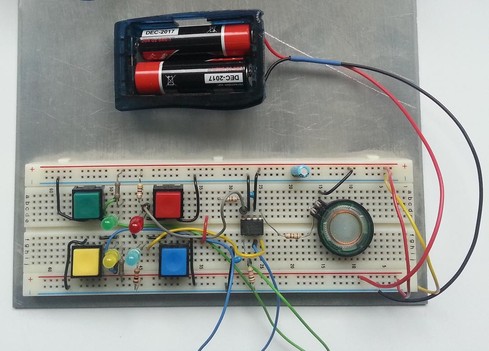
This breadboard version of a Simon Says game is a great way to try your skills on a new microcontroller platform. The eight-pin chip seen in the center of the board is an LPC810 microcontroller which [Hartmut Wendt] is just getting started with. It’s a rare example of a low-pin count DIP package for an ARM device (Cortext M0). The breadboard friendly footprint makes it easy to work with, but you could pull off the same build with a dev board like one of the STM discovery offerings or the Stellaris Launchpad boards.

Why is this a good way to learn? It involves input, output, and generating waveforms which we’d assume means timers (we didn’t dig through the source code which is available form the page linked above). Each colored button has a matching LED which blinks out the pattern which you must replicate to keep the game going; you know how Simon Says works, right?. At the same time a different pitch is played by the speaker on the right.

Another good exercise would be to take [Hartmut’s] code and port it for a different chip, be it ARM or otherwise.

Continue reading “Simon Says Learn How To Program ARM Chips”

R2R Ladder Connects Multiple Buttons To One ADC Pin

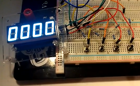
If you’ve run out of I/O pins on a project and need a way to add user input you can find a slew of port expanders that work with various communications protocols like I2C and 1-Wire. But if you just want to add in some buttons without reaching for an extra IC you’ll love this hack. [John Boxall] shows how to add four buttons using one ADC pin.

The concept is nothing new. The buttons make up an R2R resistive ladder. When one of them is pressed, it completes the circuit for a voltage divider. The results are measured by the analog-to-digital converter of an IC to tell which button was pressed. The difficult part is calculating the resistor values. [John] is using eight resistors made up of just two different values. Every button and every combination of buttons has a unique voltage result which can be discerned by the chip. He even made a truth table so you don’t have to.

The example circuit seen in the video after the break uses an Arduino. But this concept is directly applicable to any microcontroller. And it should be quite easy to use an ADC interrupt to drive all of the button-read events. Continue reading “R2R Ladder Connects Multiple Buttons To One ADC Pin”