A lot of consumer gadgets use touch sensors now. It is a cheap and reliable way to replace a variety of knobs and switches on everything from headphones to automobiles. However, creating a custom touch controller for a one-off project can be daunting. A recent ACM paper shows how just about any capacitive sensor can work as a multitouch sensor with nothing more than an Arduino although a PC running processing interprets the data for higher-level functions.
The key is that the Arduino excites the grid using PWM and then examines the signal coming out of the grid. Finger poking changes the response quite a bit and the Arduino can sense it using the analog to digital converters onboard. You can find the actual software kit online. The tutorial document is probably more interesting than the ACM paper if you only want to use the kit.
The optimum drive frequency is 10 MHz. The examples rely on harmonics of a lower frequency PWM signal to get there. The analog conversion, of course, isn’t that fast but since your finger touch rate is relatively slow, they treat the signal as an amplitude-modulated input which is very easy to decode.
The sensors can be conductive ink, thread, or copper strips. There are several example applications, including a 3D printed bunny you can pet, a control panel on a sleeve, and an interactive greeting card.
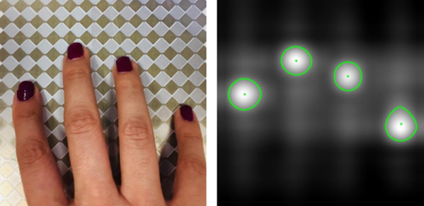
The sensor forms an image and OpenCV detects the actual touch configuration. It appears you can use the raw data from the Arduino, too, but it might be a little harder.
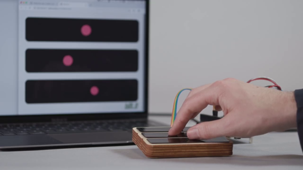
Creating capacitive touch-sensitive buttons is easy these days; many microcontrollers have cap-sense hardware built-in. This will work for simple on/off control, but what if you want a linear, position-sensitive input, like you’d find on a computer touchpad or your smartphone screen? Not so easy — at least until now. Trill is a family of capacitive touch sensors you can add to your projects as a linear slider, a square touchpad, or by creating your own touch surface.
Trill was created by the same team that designed Bela, an embedded platform for low-latency interactive applications, especially with audio. The new trio of Trill sensors rely on capacitive sensing to track finger movement, and communicate over I2C with your microcontroller or development board of choice. The Trill I2C library targets Arduino and Bela, but should be easy to port to any I2C host.
The hardware and software are both open-source — or will be as the Kickstarter that launched this morning has already met its goal. The firmware for the Cypress CY8C20636A (PDF) controller that powers these sensors will be released CC-BY-NC-SA. But, starting with the controller itself sounds like a lot of work that Trill has already done for you, so let’s have a look at what we know so far, along with a healthy dose of speculation.
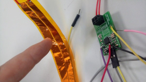
Year on year, microcontrollers and development platforms are shipping with ever-increasing feature sets. In the distant past, if you wanted an analog to digital converter or a PWM driver, you had to tack extra ICs on to your design. Nowadays, it’s all baked in at the factory. Of course, you may still find yourself working with a platform that lacks capacitive touch inputs. That’s no problem, though – you can do it all without dedicated hardware anyway!
Capacitive touch sensing works by creating an RC oscillator, and allowing the user to affect the capacitance in the circuit through touch or proximity. By sensing the changes in the frequency of the oscillator, it’s possible to determine whether the object or pad is being touched or not. As the capacitance changes can be small, sometimes it’s desired to use a high frequency oscillator, and then pass the output through a frequency divider, which allows changes to be measured more easily by a slower microcontroller.
[Gabriel] does a great job of both explaining the theory involved, as well as presenting a practical way to achieve this with basic hardware. If you need to add touch sensitivity to an existing or otherwise limited platform, this is an easy way to go about doing it. There are definitely some interesting things you can do with the technology, after all.
Rotary encoders are critical to many applications, even at the hobbyist level. While considering his own rotary encoding needs for upcoming projects, it occurred to [Jan Mrázek] to try making his own DIY capacitive rotary encoder. If successful, such an encoder could be cheap and very fast; it could also in part be made directly on a PCB.
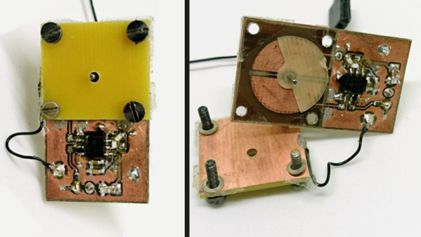
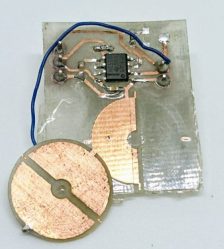
First prototype, two etched plates with transparent tape as dielectric material. Disc is 15 mm in diameter.
The encoder design [Jan] settled on was to make a simple adjustable plate capacitor using PCB elements with transparent tape as the dielectric material. This was used as the timing element for a 555 timer in astable mode. A 555 in this configuration therefore generates a square wave that changes in proportion to how much the plates in the simple capacitor overlap. Turn the plate, and the square wave’s period changes in response. Response time would be fast, and a 555 and some PCB space is certainly cheap materials-wise.
The first prototype gave positive results but had a lot of problems, including noise and possibly a sensitivity to temperature and humidity. The second attempt refined the design and had much better results, with an ESP32 reliably reading 140 discrete positions at a rate of 100 kHz. It seems that there is a tradeoff between resolution and speed; lowering the rate allows more positions to be reliably detected. There are still issues, but ultimately [Jan] feels that high-speed capacitive encoders requiring little more than some PCB real estate and some 555s are probably feasible.
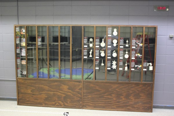
Museum exhibits are difficult to make, and they’re always breaking down; especially the interactive ones. This is a combination of budget, building a one-off, and the incredibly harsh abuse they take from children.
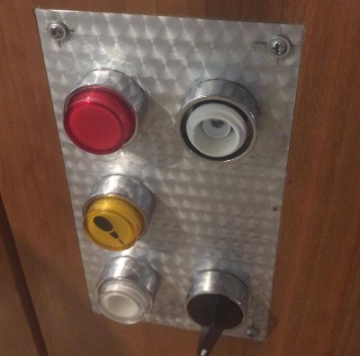
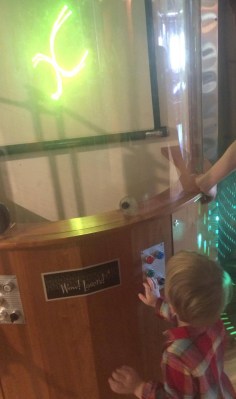
My first exhibit is an interactive laser show that turns waveforms from music into laser patterns, and different types of music have very different patterns. I knew from talking to the museum staff that industrial buttons were a necessity, but it turns out that industrial buttons are made under the assumption that tiny creatures won’t be constantly mashing, twisting, and (ew ew ew) licking the buttons. After a while, the buttons (and poor knob) were trashed.
The button face has been removed, and the knob is spinning freely.
Buttons at toddler level are in a vulnerable position.
The second exhibit is also interactive, but in this case it’s just a simple button that turns on a thing for a while, then shuts it off. You can read more about the Periodic Table of Motion on the project page. Here I thought; let’s use capacitive touch, put the sensor behind two layers of acrylic for protection, and then there won’t be any moving parts to break. I built a bunch of units, tested it for weeks, then installed it. Instant failure despite my diligence.
Something is different about the installation from my test environment. It might be the second layer of acrylic contributing. Maybe it’s the power supply and a strange ground issue. Maybe the room’s fluorescent lights are creating an electromagnetic field that is interrupting the sensor, or the carpet is causing static buildup that is somehow causing the midichlorians to reverse polarity and discharge through the base plate of prefabulated aluminite. In some of the cells, the button doesn’t work. In other cells it is extremely sensitive. In one column of the table (columns share a common piece of acrylic among 5 cells), a single touch will trigger all 5.
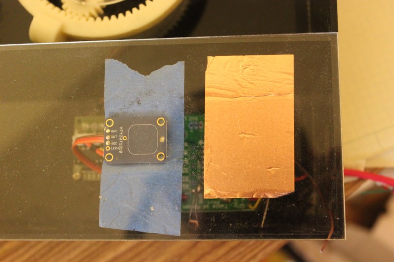
The circuit is an ATtiny with a 2.2M resistor between two pins, one of which connects via a short wire to a soldered connection to a piece of copper tape on the underside of an acrylic piece. The ATtiny is using the capsense library, which has features for automatic recalibration. Because of the way it is installed, I can’t reprogram them to adjust their sensitivity while inside the enclosure, so tweaking them post-install is not an option. I thought I could isolate the problem and use an existing capacitive touch sensor breakout of the AT42QT1010 hooked up to just power, but it had the exact same issue, meaning it’s either the power supply, the enclosure, or the room.
Side-by-side tests of copper tape+Arduino and AT42QT1010 had similar problems.
There are three paths I can go down now:
Find the problem and solve it
Switch to a photoresistor
Petition Hackaday for a better solution
Finding the problem and solving it will be a long and difficult path, especially since the museum environment is somehow and inexplicably different from the test environment. The photoresistor option has promise; when the user puts their hand over the paper button the light level changes. Some early testing indicates that it is easy to detect instantaneous change, and a trailing average and adjusting threshold make it robust enough for changing lighting conditions throughout the day. Further, it’s a simple change to the code, and the existing circuit board will accommodate the adjustment.
As for the third option…
What have you done for child-compatible touch interfaces that are robust enough to handle uncertain environments and harsh abuse? What buttons, knobs, and other interactive elements have you used?
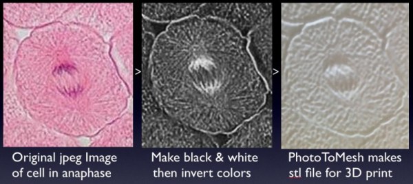
Cell biology professor [Mike] has created a way for blind students to decipher microscope slides using 3D prints and the magic of capacitive sensing. His write-up focuses on a slide showing the anaphase stage of mitosis in whitefish blastula, a popular choice for studying cell division. When a student touches a certain area of the print, the capacitive sensor triggers audio playback to tell them what they’re feeling.
[Mike] started by turning a 2D image of a cell into a 3D print. To do this, he made the image black and white, and then inverted the colors so that the 3D print’s topography will correspond correctly. The talking part is handled by an Arduino Duemilanove and a Spikenzie voice shield. The latter has a somewhat limited amount of space, but is more than adequate for the audio labels [Mike] made, which are all less than three seconds long.
A hard copy of the 2D file comes in handy for making sure the cap sensors are in the right places. To make those, [Mike] cut up some floor protector pads and covered the sticky side with copper tape. These are held on the 2D image with double-sided tape. The 3D print sits on top, separated by more furniture pads at the corners. He labeled this scientific sandwich model with a 3D printed Braille label that reads ‘anaphase’. [Mike] has made the referenced STL file along with a few others available at the National Institutes of Health’s 3D print exchange site.
Are you the mutant savior? Are you prepared for the robot uprising of 2084? Have you accepted robotron into your life? The Church of Robotron is now conducting training, testing, and confession at the new window altar in downtown Portland.
The Church of Robotron is the fake totally legit religion based on the classic arcade game prophecy Robotron 2084. In keeping with the church’s views on community outreach and missionary work, a Robotron altar has been installed at the Diode Gallery for electronic arts.
The altar consists of a system running Robotron 2084 with capacitive sensing controls built by DorkbotPDX’s own [Phillip Odom]. He’s using the same techniques featured in his capacitive sensing workshop, allowing the game to be played 24 hours a day. There are also monitors displaying the leaderboard and tenants of the Church of Robotron.