Admittedly, not a lot of people have a regular need to varnish coils. It’s mainly something that Tesla coil builders and other high-voltage experimenters are concerned with. But since that group probably constitutes a not insignificant fraction of the Hackaday audience, and because there are probably more applications for this homebrew coil varnishing setup, we figured it would be a good idea to share it.
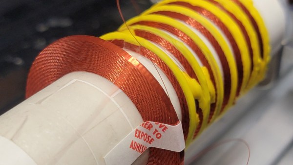
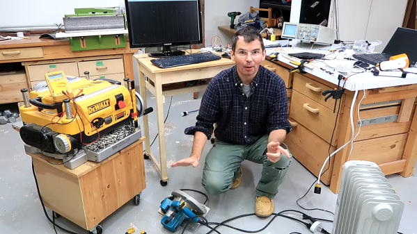
For [Mads Barnkob], coil maintenance isn’t something to take lightly. If you check out his Kaizer Power Electronics channel on YouTube, you’ll see that he has quite a collection of large, powerful Tesla coils, some of which are used for demos and shows, and others that seem to be reserved mainly for blowing stuff up. To prevent one of his coils from joining the latter group, keeping the coat of insulating varnish on the secondary coil windings in tip-top condition is essential.
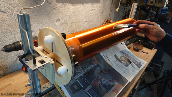
The setup seen in the video below helps with that tedious chore. Built entirely from scraps and junk bin parts, the low-speed, low-precision lathe can be set up to accommodate coils of all sizes. In use, the lathe turns the coil very slowly, allowing [Mads] to apply an even coat of varnish over the coil surface, and to keep it from sagging while it dries.
[Mads]’ setup is probably not great for coil winding as it is, but for coil maintenance, it’s just the thing. If your needs are more along the lines of a coil winder, we’ve got a fully automated winder that might work for you.
Continue reading “Junkbox Build Keeps Tesla Coils Perfectly Varnished”