Designing a circuit is a lot easier on paper, where components have well-defined values, or lacking that, at least well-defined tolerances. Unfortunately, even keeping percentage tolerances in mind isn’t always enough to make sure that circuits work correctly in the real world, as [Tahmid] demonstrates by diagnosing a buck converter with an oddly strong voltage ripple in the output.
Some voltage ripple is an inherent feature of the buck converter design, but it’s inversely proportional to output capacitance, so most designs include a few smoothing capacitors on the output side. However, at 10 V and a 50% duty cycle, [Tahmit]’s converter had a ripple of 0.75 V, significantly above the predicted variation of 0.45 V. The discrepancy was even greater at 20 V.
The culprit was the effect of higher voltages on the ceramic smoothing capacitors: as the voltage increases, the dielectric barrier in the capacitors becomes less permittive, reducing their capacitance. Fortunately, unlike in the case of electrolytic capacitors, the degradation of ceramic capacitors performance with increasing voltage is usually described in specification sheets, and doesn’t have to be manually measured. After finding the reduced capacitance of his capacitors at 10 V, [Tahmid] calculated a new voltage ripple that was only 14.5% off from the true value.
Anyone who’s had much experience with electronics will have already learned that passive components – particularly capacitors – aren’t as simple as the diagrams make them seem. On the bright side, they are constantly improving.
dielectric19 Articles
PCB Dielectric Constant Measurements, Three Ways
FR4 is FR4, right? For a lot of PCB designs, the answer is yes — the particular characteristics of the substrate material don’t impact your design in any major way. But things get a little weird up in the microwave range, and having one of these easy methods to measure the dielectric properties of your PCB substrate can be pretty handy.
The RF reverse-engineering methods [Gregory F. Gusberti] are deceptively simple, even if they require some fancy test equipment. But if you’re designing circuits with features like microstrip filters where the permittivity of the substrate would matter, chances are pretty good you already have access to such gear. The first method uses a ring resonator, which is just a PCB with a circular microstrip of known circumference. Microstrip feedlines approach but don’t quite attach to the ring, leaving a tiny coupling gap. SMA connectors on the feedline connect the resonator to a microwave vector network analyzer in S21 mode. The resonant frequencies show up as peaks on the VNA, and can be used to calculate the effective permittivity of the substrate.
Method two is similar in that it measures in the frequency domain, but uses a pair of microstrip stubs of different lengths. The delta between the lengths is used to cancel out the effect of the SMA connectors, and the phase delay difference is used to calculate the effective permittivity. The last method is a time domain measurement using a single microstrip with a couple of wider areas. A fast pulse sent into this circuit will partially reflect off these impedance discontinuities; the time delay between the reflections is directly related to the propagation speed of the wave in the substrate, which allows you to calculate its effective permittivity.
One key takeaway for us is the concept of effective permittivity, which considers the whole environment of the stripline, including the air above the traces. We’d imagine that if there had been any resist or silkscreen near the traces it would change the permittivity, too, making measurements like these all the more important.
Continue reading “PCB Dielectric Constant Measurements, Three Ways”
Making PCB Strip Filter Design Easy To Understand
We’ve always been fascinated by things that perform complex electronic functions merely by virtue of their shapes. Waveguides come to mind, but so do active elements like filters made from nothing but PCB traces, which is the subject of this interesting video by [FesZ].
Of course, it’s not quite that simple. A PCB is more than just copper, of course, and the properties of the substrate have to be taken into account when designing these elements. To demonstrate this, [FesZ] used an online tool to design a bandpass filter for ADS-B signals. He designed two filters, one using standard FR4 substrate and the other using the more exotic PTFE.
He put both filters to the test, first on the spectrum analyzer. The center frequencies were a bit off, but he took care of that by shortening the traces slightly with a knife. The thing that really stood out to us was the difference in insertion loss between the two substrates, with the PTFE being much less lossy. The PTFE filter was also much more selective, with a tighter pass band than the FR4. PTFE was also much more thermostable than FR4, which had a larger shift in center frequency and increased loss after heating than the PTFE. [FesZ] also did a more real-world test and found that both filters did a good job damping down RF signals across the spectrum, even the tricky and pervasive FM broadcast signals that bedevil ADS-B experimenters.
Although we would have liked a better explanation of design details such as via stitching and trace finish selection, we always enjoy these lessons by [FesZ]. He has a knack for explaining abstract concepts through concrete examples; anyone who can make coax stubs and cavity filters understandable has our seal of approval.
Continue reading “Making PCB Strip Filter Design Easy To Understand”
Learning About Capacitors By Rolling Your Own Electrolytics
Ever wonder what’s inside an electrolytic capacitor? Many of us don’t, having had at least a partial glimpse inside after failure of the cap due to old age or crossed polarity. The rest of us will have to rely on this behind-the-scenes demo to find out what’s inside those little aluminum cans.
Perhaps unsurprisingly, it’s more aluminum, at least for the electrolytics [Denki Otaku] rolled himself at the Nippon Chemi-Con R&D labs. Interestingly, both the anode and cathode start as identical strips of aluminum foil preprocessed with proprietary solutions to remove any oils and existing oxide layers. The strips then undergo electrolytic acid etching to create pits to greatly increase their surface area. The anode strips then get anodized in a solution of ammonium adipate, an organic acid that creates a thin aluminum oxide layer on the strip. It’s this oxide layer that actually acts as the dielectric in electrolytic capacitors, not the paper separator between the anode and cathode strips.
Winding the foils together with the paper separator is pretty straightforward, but there are some neat tricks even at the non-production level demonstrated here. Attachment of lead wires to the foil is through a punch and crimp operation, and winding the paper-foil sandwich is actually quite fussy, at least when done manually. No details are given on the composition of the electrolyte other than it contains a solvent and an organic acid. [Denki] took this as an invitation to bring along his own electrolyte: a bottle of Coke. The little jelly rolls get impregnated with electrolyte under vacuum, put into aluminum cans, crimped closed, and covered with a heat-shrink sleeve. Under test, [Denki]’s hand-rolled caps performed very well. Even the Coke-filled caps more or less hit the spec on capacitance; sadly, their ESR was way out of whack compared to the conventional electrolyte.
There are plenty more details in the video below, although you’ll have to pardon the AI voiceover as it tries to decide how to say words like “anode” and “dielectric”; it’s a small price to pay for such an interesting video. It’s a much-appreciated look at an area of the industry that few of us get to see in detail.
Continue reading “Learning About Capacitors By Rolling Your Own Electrolytics”
New Part Day: Exotic Filament For RF Dielectric Structures
The world of microwave RF design appears to the uninitiated to be full of unimaginably exotic devices, as engineers harness the laws of physics to tame radio signals to their will. Among the weapons in their arsenal are materials of known dielectric properties, from which can be made structures with the desired effects on RF that encounters them. This has traditionally been a difficult and expensive process, but it’s one now made much easier by the availability of 3D printer filaments with a range of known dielectric values.
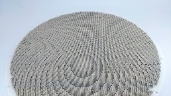
It’s best to think of the structures which can be designed using these materials as analagous to Fresnel lenses we’re all used to in the light domain. The example piece given by Microwave Journal is a metasurface for use in a steerable antenna, something that would be a much more difficult piece of work by more traditional means.
Normally when we inform you of a new special filament we’d expect it to be more costly than standard PLA, but this filament is in a class of its own at 275 euros per kilogram. So the interest for most readers will probably be more in the technology than the expectation of use, but even then we can see that there will still be microwave experimenters in our range who might be tempted by its unique properties. We look forward to what is developed using it.
Via Microwave Journal. Thanks to [Eric Mockler] for the tip!
Enjoy The Beauty Of Corona Discharge With This Kirlian Photography Setup
In our age of pervasive digital media, “pics or it didn’t happen” is a common enough cry that most of us will gladly snap a picture of pretty near anything to post online. So if you’re going to take a picture, it may as well be as stunning as these corona discharge photographs made with a homebrew Kirlian photography rig.
We know, Kirlian photography has a whole “woo-woo” vibe to it, associated as it has been with paranormal investigations and the like. But [Hyperspace Pirate] isn’t flogging any of that; in fact, he seems way more interested in the electronics of the setup than anything else. The idea with Kirlian photography is basically to capacitively couple a high-voltage charge across a dielectric, which induces an electrostatic discharge to a grounded object. The result is a beautiful purple discharge, thanks to atmospheric nitrogen, that outlines the object being photographed.
[Pirate]’s first attempt at a Kirlian rig used acrylic as a dielectric, which proved to be susceptible to melting. We found this surprising since we’ve seen [Jay Bowles] successfully use acrylic for his Kirlian setup. Version 2 used glass as a dielectric — right up until he tried to drill a fill port into the glass. (Important safety tip: don’t try to drill holes in tempered glass.) Version 3 used regular glass and a 3D-printed frame to make the Kirlian chamber; filled with saltwater and charged up with a homebrew Tesla coil, the corona discharge proved enough to char fingertips and ignite paper. It also gave some beautiful results, which can be seen starting at around the 7:40 mark in the video below.
We loved the photos, of course, but also appreciated the insights into the effects of inductance on the performance of this setup. And that first homebrew flyback transformer [Hyperspace Pirate] built was pretty cool, too.
Continue reading “Enjoy The Beauty Of Corona Discharge With This Kirlian Photography Setup”
Homemade EDM Machine Moves From Prototype To Production
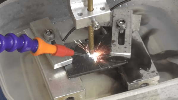
Of all the methods of making big pieces of metal into smaller pieces of metal, perhaps none is more interesting than electrical discharge machining. EDM is also notoriously fussy, what with having to control an arc discharge while precisely positioning the tool relative to the workpiece. Still, some home gamers give it a whirl, and we love to share their successes, like this work-in-progress EDM machine. (Video, embedded below.)
We’ve linked [Andy]’s first videos below the break, and we’d expect there will be a few more before all is said and done. But really, for being fairly early in the project, [Andy] has made a lot of progress. EDM is basically using an electric arc to remove material from a workpiece, but as anyone who has unintentionally performed EDM on, say, a screwdriver by shorting it across the terminals in a live outlet box, the process needs to be controlled to be useful.
Part 1 shows the start of the build using an old tap burning machine, a 60-volt power supply, and a simple pulse generator. This was enough to experiment with the basics of both the mechanical control of electrode positioning, and the electrical aspects of getting a sustained, useful discharge. Part 2 continues with refinements that led very quickly to the first useful parts, machined quickly and cleanly from thin stock using a custom tool. We’ll admit to being impressed — many EDM builds either never get to the point of making simple holes, or stop when progressing beyond that initial success proves daunting. Of course, when [Andy] drops the fact that he made the buttons for the control panel on his homemade injection molding machine, one gets the feeling that anything is possible.
We’re looking forward to more on this build. We’ve seen a few EDM builds before, but none with this much potential.
Continue reading “Homemade EDM Machine Moves From Prototype To Production”


