If you’re really interested in aircraft and flying, there are many ways to explore that interest. There are models of a wide range of sizes and complexities that are powered and remote-controlled, and even some small lightweight aircraft that can get you airborne yourself for a minimum of expense. If you’re lucky enough to have your own proper airplane, though, and you’re really into open source projects, you can also replace your airplane’s avionics kit with your own open source one.
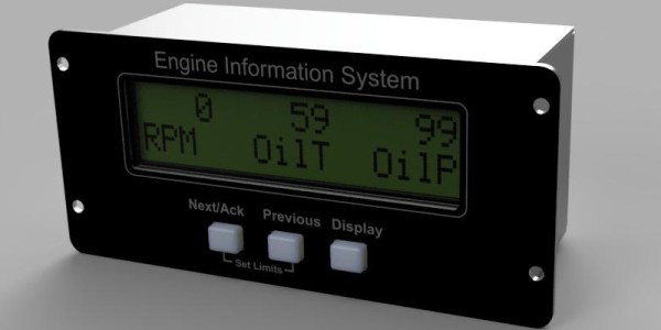
Avionics are the electronics that control and monitor the aircraft, and they’re a significant part of the aircraft’s ability to fly properly. This avionics package from [j-omega] (who can also be found on hackaday.io) will fit onto a small aircraft engine and monitor things like oil temperature, RPM, coolant temperature, and a wide array of other features of the engine. It’s based on an ATmega microcontroller, and has open-source schematics for the entire project and instructions for building it yourself. Right now it doesn’t seem like the firmware is available on the GitHub page yet, but will hopefully be posted soon for anyone who’s interested in an open-source avionics package like this.
The project page does mention that this is experimental as well, so it might not be advised to use in your own personal aircraft without some proper testing first. That being said, if you’ve heard that warning and have decided just to stay on the ground, it’s possible to have a great experience without getting in a real airplane at all.
The Wankel rotary engine is known for its troubled life in the mainstream automotive industry, its high power-to-weight ratio, and the intoxicating buzz it makes at full tilt. Popular with die-hard enthusiasts and punishing to casual owners, it stands as perhaps the most popular alternative internal combustion design to see the light of day. There are myriad diagrams out there to explain its operation, but what if you could see inside?
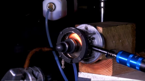
The video comes courtesy of [Warped Perception], and features a small Wankel rotary engine intended for model aircraft. The engine’s end plate is removed and replaced with a transparent plate, making the combustion process visible. Add in a high-speed camera, and you’ve got a recipe for a great technical video.
It starts with a basic explanation of how the Wankel rotary power cycle operates, before cutting to the glorious slow-motion shots of the engine in operation. It also highlights several techniques useful for producing this type of video, such as painting surrounding components black to make it easier to image the parts of interest. The visuals are amazing and very clearly show the manner in which the intake, compression, power and exhaust strokes function in the engine.
Some folks just can’t leave well enough alone, and that often ends up being a good thing. Such is the case with this 3D-printed compressed air engine, which just keeps getting better.
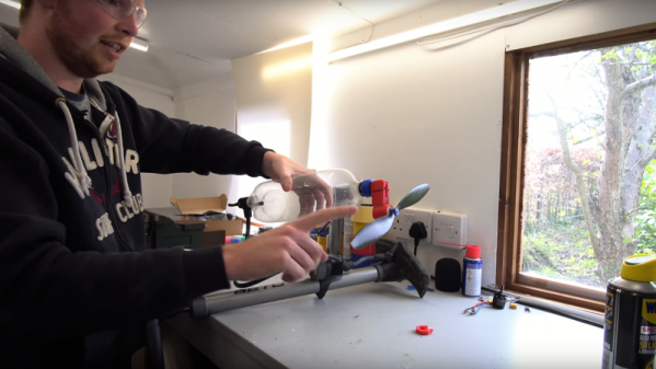
The design has changed a lot since we first covered [Tom Stanton]’s attempts at reviving the powerplant from the glory days of the Air Hogs line of toys, which he subsequently built a plane around. The engine was simple, with a ball valve that admitted air into the cylinder when a spring mounted to the top of the piston popped it out of the way. That spring has always bothered [Tom], though, compelling him to go back to the drawing board. He wanted to replace the ball valve with one actuated by a cam and pushrod. This would increase the complexity of the engine quite a bit, but with the benefit of eliminating the fail point of the spring. With a few iterations in the design, he was able to relocate the ball valve, add a cam to the crankshaft, and use a pushrod to open the valve. The new design works much better than the previous version, sounding more like a lawnmower than a 3D-printed engine should. Check out the design process and some tests in the video below.
Additive manufacturing has come a long way in a short time, and the parts you can turn out with some high-end 3D-printers rival machined metal in terms of durability. But consumer-grade technology generally lags the good stuff, so there’s no way you can 3D-print internal combustion engine parts on a run of the mill printer yet, right?
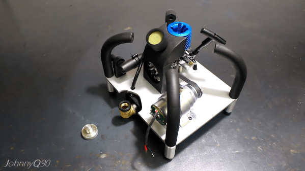
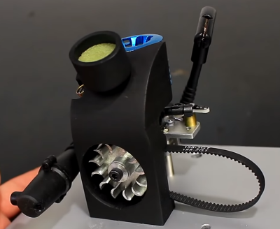
As it turns out, you can at least 3D-print connecting rods, if both the engine and your expectations are scaled appropriately. [JohnnyQ90] loves his miniature nitro engines, which we’ve seen him use to power both a rotary tool and a hand drill before. So taking apart a perfectly good engine and replacing the aluminum connecting rod with a PETG print was a little surprising. The design process was dead easy with such a simple part, and the print seemed like a reasonable facsimile of the original when laid side-by-side. But there were obvious differences, like the press-fit bronze bearings and oil ports in the crank and wrist ends of the original part, not to mention the even thickness along the plastic part instead of the relief along the shaft in the prototype.
Nonetheless, the rod was fitted into an engine with a clear plastic cover that lets us observe the spinning bits right up to the inevitable moment of failure, which you can see in the video below. To us it looks like failing to neck down the shaft of the rod was probably not a great idea, but the main failure mode was the bearings, or lack thereof. Still, we were surprised how long the part lasted, and we can’t help but wonder how a composite connecting rod would perform.
Still in the mood to see how plastic performs in two-stroke engines? Break out the JB Weld.
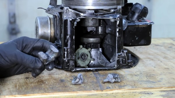
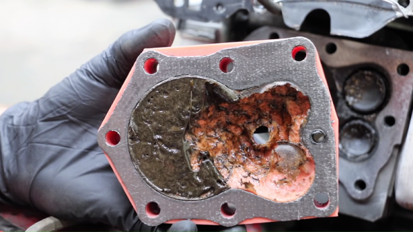
A few weeks ago an incredible video of an engine exploding started making the rounds on Facebook. This particular engine was thankfully in a dyno room, rather than sitting a couple of feet away from a driver on a track. We’ve all seen engine carnage videos before, but this one stands out. This diesel engine literally rips itself apart, with the top half of the engine flipping and landing on one side of the room while the bottom half sits still spinning on the dyno frame.
Building performance engines is part science, part engineering, and part hacking. While F1 racing teams have millions of dollars of test and measurement equipment at their disposal, smaller shops have to operate on a much lower budget. In this case, the company makes their modifications, then tests things out in the dyno room. Usually, the tests work out fine. Sometimes though, things end spectacularly, as you can see with this diesel engine.
The engine in question belongs to Firepunk diesel, a racing team. It started life as a 6.7 liter Cummins diesel: the same engine you can find in Dodge Ram pickup trucks. This little engine wasn’t content to chug around town, though. The Firepunk team builds performance engines — drag racing and tractor pulling performance in this case. Little more than the engine block itself was original on this engine. Let’s take a deeper look.
One of the most important considerations when flying remote-controlled airplanes is weight. Especially if the airplane has a motor, this has a huge potential impact on weight. For this reason, [gzumwalt] embarked on his own self-imposed challenge to build an engine with the smallest weight and the lowest parts count possible, and came away with a 25-gram, 8-part engine.
The engine is based around a single piston and runs on compressed air. The reduced parts count is a result of using the propeller axle as a key component in the engine itself. There are flat surfaces on the engine end of the axle which allow it to act as a valve and control its own timing. [gzumwalt] notes that this particular engine was more of a thought experiment and might not actually produce enough thrust to run an airplane, but that it certainly will spark up some conversations among RC enthusiasts.
The build is also one of the first designs in what [gzumwalt] hopes will be a series of ever-improving engine designs. Perhaps he should join forces with this other air-powered design that we’ve just recently featured. Who else is working on air-powered planes? Who knew that this was a thing?
If you have a car parked outside as you are reading this, the overwhelming probability is that it has a reciprocating piston engine powered by either petrol(gasoline), or diesel fuel. A few of the more forward-looking among you may own a hybrid or even an electric car, and fewer still may have a piston engine car powered by LPG or methane, but that is likely to be the sum of the Hackaday reader motoring experience.
We have become used to understanding that perhaps the era of the petroleum-fueled piston engine will draw to a close and that in future decades we’ll be driving electric, or maybe hydrogen. But visions of the future do not always materialize as we expect them. For proof of that, we only need to cast our minds back to the 1950s. Motorists in the decade following the Second World War would have confidently predicted a future of driving cars powered by jet engines. For a while, as manufacturers produced a series of prototypes, it looked like a safe bet.
Back in August, my colleague [Bryan] wrote a feature: “The Last Interesting Chrysler Had A Gas Turbine Engine“, in which he detailed the story of one of the more famous gas turbine cars. But the beautifully styled Chrysler was not the only gas turbine car making waves at the time, because meanwhile on the other side of the Atlantic a series of prototypes were taking the gas turbine in a slightly different direction.
Rover was a British carmaker that was known for making sensible and respectable saloon cars. They passed through a series of incarnations into the nationalized British Leyland empire, eventually passing into the hands of British Aerospace, then BMW, and finally a consortium of businessmen under whose ownership they met an ignominious end. If you have ever wondered why the BMW 1-series has such ungainly styling cues, you are looking at the vestiges of a Rover that never made it to the forecourt. The very successful Land Rover marque was originally a Rover product, but beyond that sector, they are not remembered as particularly exciting or technically advanced.
At the close of the Second World War though, Rover found themselves in an interesting position. One of their contributions to war production had been the gas turbine engines found in the first generation of British jet aircraft, and as part of their transition to peacetime production they began to investigate civilian applications for the technology. Thus the first ever gas turbine car was a Rover, the 1950 JET1. Bearing the staid and respectable styling of a 1950s bank manager’s transport rather than the space-age look you might expect of the first ever gas turbine car, it nonetheless became the first holder of the world speed record for a gas turbine powered car when in 1952 it achieved a speed of 152.691 MPH.
The JET1 was soon followed by a series of further jet-powered prototypes culminating in 1956’s T3 and 1961’s T4. Both of these were practical everyday cars, the T3, a sports coupé, and the T4, an executive saloon car whose styling would appear in the 1963 petrol-engined P6 model. There was also an experimental BMC truck fitted with the engine. The P6 executive car was produced until 1977, and all models were designed to have space for a future gas turbine option by having a very unusual front suspension layout with a pivot allowing the spring and damper to be placed longitudinally in the front wing.
It was not only prototypes for production cars with gas turbines that came from Rover in the 1960s though, for in 1963 they put their gas turbine into a BRM racing chassis and entered it into the Le Mans 24 hour endurance race. It returned in the 1964 season fitted with a novel rotating ceramic honeycomb heat exchanger to improve its efficiency, racing for a final season in 1965.
The fate of the gas-turbine Rovers would follow that of their equivalent cars from other manufacturers including the Chrysler covered by [Bryan]. Technical difficulties were never fully overcome, the increasing cost of fuel made gas turbine cars uneconomic to run, and meanwhile by the 1960s the piston engine had improved immeasurably over what had been available when the JET1 had been produced. The Rover P6 never received its gas turbine, and the entire programme was abandoned. Today all the surviving cars are in museums, the JET1 prototype in the Science Museum in London, and the T3, T4, and Rover-BRM racing car at the Heritage Motor Centre at Gaydon. The truck survives in private hands, having been restored, and is a regular sight at summer time shows.
As a footnote to the Rover story, in response to the development of JET1 at the start of the 1950s, their rival and later British Leyland stablemate Austin developed their own gas turbine car. If international readers find Jet1’s styling a bit quaint compared to the American jet cars, it is positively space-age when compared to the stately home styling of the Sheerline limousine to which Austin fitted their gas turbine.