Flying a glider, or similarly piloting a paraglider or hang glider, can all be pathways into aviation with a lower barrier of entry than powered flight. Sacrificing one’s engine does generate a few complexities, but can be rewarding as the pilot searches for various means of increasing altitude like ridge soaring or thermaling. You’ll need a special instrument called a variometer to know just how much altitude you’re gaining though, like this one which is built into commercially-available handheld GPS units.
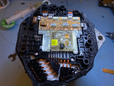
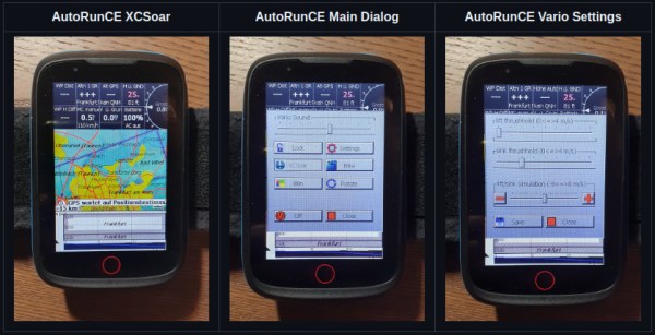
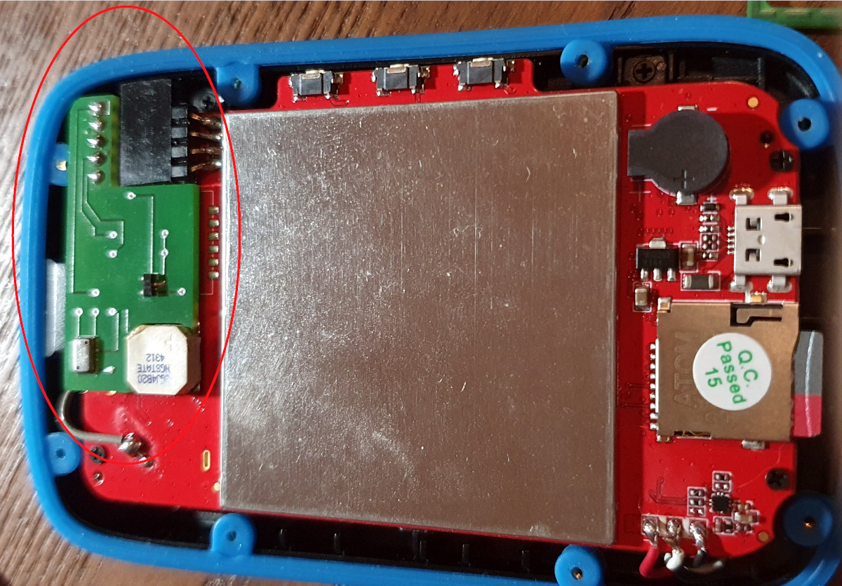 These GPS units are normally intended for use on terra firma only, but [Oganisyan] has figured out a clever way to add this flight instrumentation to these units to help when operating a paraglider. An ATmega328 paired with a pressure sensor is added to the inside of the GPS units and communicates with an available serial interface within the units. To complete the modification, a patched firmware must be installed which adds the variometer function to the display. This upgrade is compatible with a handful of GPS units as well such as the BikePilot2+ or Falk Tiger.
For those who already own one of these GPS units, this could be a cost-effective way of obtaining a variometer, especially since commercially-available variometers tailored for this sort of application can cost around $200 to $500. It is an activity sensitive to cost, though, as it offers a much more affordable option for taking to the skies than any powered craft could, with an exception made for this powered paraglider which offers the ability for powered take off and flight extension using electric-powered props.
Thanks to [MartinO] for the tip!