How Safe Is That Ultrasonic Bath For Flux Removal?

How do you clean the residual flux off your boards? There are plenty of ways to go about the job, ranging from “why bother?” to the careful application of isopropyl alcohol to every joint with a cotton swab. It seems like more and more people are turning to ultrasonic cleaners to get the job done, though, and for good reason: just dunk your board and walk away while cavitation does the work for you.

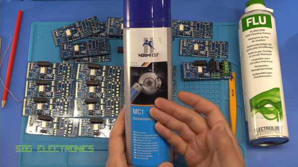
But just how safe is it to sonically blast the flux off your boards? [SDG Electronics] wanted to know, so he ran some cleaning tests to get to the bottom of things. On the face of it, dunking a PCB in an aqueous cleaning solution seems ill-advised; after all, water and electricity famously don’t mix. But assuming all the nooks and crannies of a board can be dried out before power is applied, the cleaning solution itself should be of little concern. The main beef with ultrasonic cleaning seems to be with the acoustic energy coupling with mechanical systems on boards, such as crystal oscillators or micro-electrical-mechanical systems (MEMS) components, such as accelerometers or microphones. Such components could resonate with the ultrasonic waves and be blasted to bits internally.

To test this, [SDG Electronics] built a board with various potentially vulnerable components, including the popular 32.768-kHz crystal, cut for a frequency quite close to the cleaner’s fundamental. The video below goes into some detail on the before-and-after tests, but the short story is that nothing untoward happened to any of the test circuits. Granted, no components with openings as you might find on some MEMS microphones were tested, so be careful. After all, we know that ultrasound can deal damage, and if it can levitate tiny styrofoam balls, it might just do your circuit in.

Continue reading “How Safe Is That Ultrasonic Bath For Flux Removal?”

Fail Of The Week: How Not To Re-Reflow

There’s no question that surface-mount technology has been a game-changer for PCB design. It means easier automated component placement and soldering, and it’s a big reason why electronics have gotten so cheap. It’s not without problems, though, particularly when you have no choice but to include through-hole components on your SMT boards.

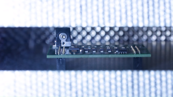
[James Clough] ran into this problem recently, and he tried to solve it by reflowing through-hole connectors onto assembled SMT boards. The boards are part of his electronic lead screw project, an accessory for lathes that makes threading operations easier and more flexible. We covered the proof-of-concept for the project; he’s come a long way since then and is almost ready to start offering the ELS for sale. The PCBs were partially assembled by the board vendor, leaving off a couple of through-hole connectors and the power jack. [James]’ thought was to run the boards back through his reflow oven to add the connectors, so he tried a few experiments first on the non-reflow rated connectors. The Phoenix-style connectors discolored and changed dimensionally after a trip through the oven, and the plastic on the pin headers loosened its grip on the pins. The female header socket and the power jack fared better, so he tried reflowing them, but it didn’t work out too well, at least for the headers. He blames poor heat conduction due to the lack of contact between the board and the reflow oven plate, and we agree; perhaps an aluminum block milled to fit snugly between the header sockets would help.

Hats off to [James] for trying to save his future customers a few steps on assembly, but it’s pretty clear there are no good shortcuts here. And we highly recommend the electronic leadscrew playlist to anyone interested in the convergence of machine tools and electronics.

Continue reading “Fail Of The Week: How Not To Re-Reflow”

Jigsaw Motor Uses PCB Coils For Radial Flux

Electric motors are easy to make; remember those experiments with wire-wrapped nails? But what’s easy to make is often hard to engineer, and making a motor that’s small, light, and powerful can be difficult. [Carl Bugeja] however is not one to back down from a challenge, and his tiny “jigsaw” PCB motor is the latest result of his motor-building experiments.

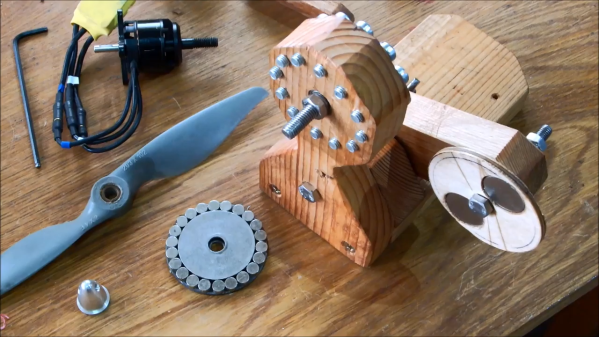
We’re used to seeing brushless PCB motors from [Carl], but mainly of the axial-flux variety, wherein the stator coils are arranged so their magnetic lines of force are parallel to the motor’s shaft – his tiny PCB motors are a great example of this geometry. While those can be completely printed, they’re far from optimal. So, [Carl] started looking at ways to make a radial-flux PCB motor. His design has six six-layer PCB coils soldered perpendicular to a hexagonal end plate. The end plate has traces to connect the coils in a star configuration, and together with a matching top plate, they provide support for tiny bearings. The rotor meanwhile is a 3D-printed cube with press-fit neodymium magnets. Check out the build in the video below.

Connected to an ESC, the motor works decently, but not spectacularly. [Carl] admits that more tweaking is in order, and we have little doubt he’ll keep optimizing the design. We like the look of this, and we’re keen to see it improved.

Continue reading “Jigsaw Motor Uses PCB Coils For Radial Flux”

The Fascinating World Of Solder Alloys And Metallurgy

Solder is the conductive metal glue that one uses to stick components together. If you get the component and the PCB hot enough, and melt a little solder in the joint, it will stay put and conduct reliably. But it’s far from simple.

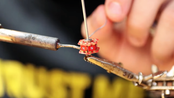
There are many different solder alloys, and even the tip of the soldering iron itself is a multi-material masterpiece. In this article, we’ll take a look at the metallurgy behind soldering, and you’ll see why soldering tip maintenance, and regular replacement, is a good idea. Naturally, we’ll also touch upon the role that lead plays in solder alloys, and what the effect is of replacing it with other metals when going lead-free. What are you soldering with? Continue reading “The Fascinating World Of Solder Alloys And Metallurgy”

Hacking The Ionosphere, For Science

Imagine what it must have been like for the first human to witness an aurora. It took a while for our species to migrate from its equatorial birthplace to latitudes where auroras are common, so it was a fairly recent event geologically speaking. Still, that first time seeing the shimmers and ribbons playing across a sky yet to be marred by light pollution must have been terrifying and thrilling, and like other displays of nature’s power, it probably fueled stories of gods and demons. The myths and legends born from ignorance of what an aurora actually represents seem quaint to most of us, but it was as good a model as our ancestors needed to explain the world around them.

Our understanding of auroras needs to be a lot deeper, though, because we now know that they are not only a beautiful atmospheric phenomenon but also a critical component in the colossal electromagnetic system formed by our planet and our star. Understanding how it works is key to everything from long-distance communication to keeping satellites in orbit to long-term weather predictions.

But how exactly does one study an aurora? Something that’s so out of reach and so evanescent seems like it would be hard to study. While it’s not exactly easy science to do, it is possible to directly study auroras, and it involves some interesting technology that actually changes them, somehow making the nocturnal light show even more beautiful.

Continue reading “Hacking The Ionosphere, For Science”

Get To Know The Physics Behind Soldering And The Packaging Of ICs

Often it feels as if soldering is deemed to be more of an art form than something that’s underpinned by the cold, hard reality of physics and chemistry. From organic chemistry with rosin, to the material properties of fragile gold bond wires and silicon dies inside IC packages and the effects of thermal stress on the different parts of an IC package, it’s a complicated topic that deserves a lot more attention than it usually gets.

A casual inquiry around one’s friends, acquaintances, colleagues and perfect strangers on the internet usually reveals the same pattern: people have picked up a soldering iron at some point, and either figured out what seemed to work through trial and error, or learned from someone else who has learned what seemed to work through trial and error. Can we say something scientific about soldering?

Continue reading “Get To Know The Physics Behind Soldering And The Packaging Of ICs”

Ask Hackaday: Get The Lead Out Or Not?

For most of the history of industrial electronics, solder has been pretty boring. Mix some lead with a little tin, figure out how to wrap it around a thread of rosin, and that’s pretty much it. Sure, flux formulations changed a bit, the ratio of lead to tin was tweaked for certain applications, and sometimes manufacturers would add something exotic like a little silver. But solder was pretty mundane stuff.

Source: RoHS Guide

Then in 2003, the dull gray world of solder got turned on its head when the European Union adopted a directive called Restriction of Hazardous Substances, or RoHS. We’ve all seen the little RoHS logos on electronics gear, and while the directive covers ten substances including mercury, cadmium, and hexavalent chromium, it has been most commonly associated with lead solder. RoHS, intended in part to reduce the toxicity of an electronic waste stream that amounts to something like 50 million tons a year worldwide, marked the end of the 60:40 alloy’s reign as the king of electrical connections, at least for any products intended for the European market, when it went into effect in 2006.

Continue reading “Ask Hackaday: Get The Lead Out Or Not?”