The number of interesting and innovative mechanisms that 3D printing has enabled always fascinates us, and it’s always a treat when one of them shows up in our feeds. This axial flux magnetic gearbox is a great example of such a mechanism, and one that really makes you think about possible applications.
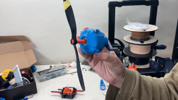
The principles of [Retsetman]’s gearbox are simple for anyone who has ever played with a couple of magnets to understand, since it relies on that powerful attractive and repulsive force you feel when magnets get close to each other. Unlike his previous radial flux gearbox, which used a pair of magnet-studded cylindrical rotors nested one inside the other, this design has a pair of disc-shaped printed rotors that face each other on aligned shafts. Each rotor has slots for sixteen neodymium magnets, which are glued into the slots in specific arrangements of polarity — every other magnet for the low-speed rotor, and groups of four on the high-speed rotor. Between the two rotors is a fixed flux modulator, a stator with ten ferromagnetic inserts screwed into it.
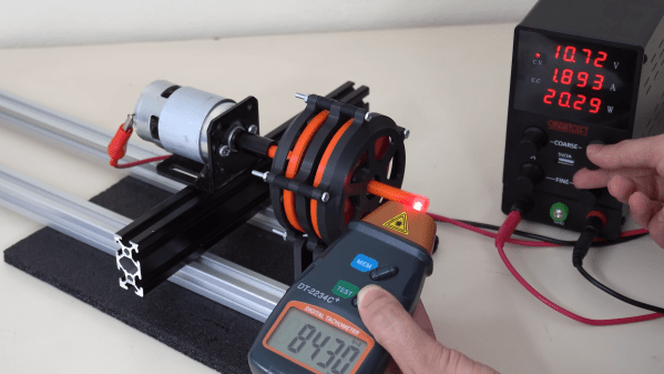
In operation, which the video below demonstrates nicely, the magnetic flux is coupled between the rotors by the steel inserts in the stator so that when one rotor moves, the other moves at a 4:1 (or 1:4) ratio in the opposite direction. [Retsetman] got the gearbox cranked up to about 8,500 RPM briefly, but found that extended operation at as little as 4,000 RPM invited disaster not due to eddy current heating of the inserts or magnets as one might expect, but from simple frictional heating of the rotor bearings.
Torque tests of the original gearbox were unimpressive, but [Retsetman]’s experiments with both laminated stator inserts and more powerful magnets really boosted the output — up to a 250% improvement! We’d also like to see what effect a Halbach array would have on performance, although we suspect that the proper ratios between the two rotors might be difficult to achieve.
Continue reading “Magnetic Gearbox, Part 2: Axial Flux Improves Performance”


 There is also a separate