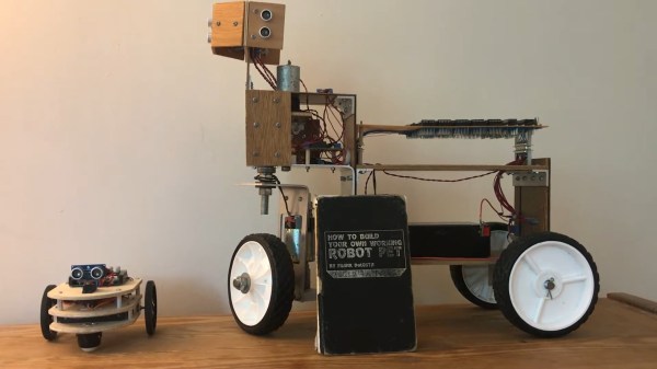
Edge-Mounted LEDs Make This Spherical POV Look Fantastic

For as many of them as we’ve seen, we still love a good persistence of vision display project. There’s something fascinating about the combination of movement and light creating the illusion of solid surfaces, and there’s always fun to be had in electromechanical aspects of a POV build. This high-resolution spherical POV display pushes all those buttons, and more.

Called “Flicker” for obvious reasons by its creator [Dan Foisy], this POV display started with a pretty clear set of goals in terms of resolution and image quality, plus the need to support animated images, all in a spherical form factor. These goals dictated the final form of the display — a PCB disc spinning vertically. The shaft has the usual slip rings for power distribution and encoders for position feedback. The PCB, though, is where the interesting stuff is.

[Dan] chose to use an FPGA to slice and dice the images, which are fed from a Raspberry Pi’s HDMI port, to the LED drivers. And the LEDs themselves are pretty slick — he found parts with 1.6 mm lead spacing, making them a perfect fit for mounting on the rim of the PCB rather than on either side. A KiCAD script automated the process of laying out the 256 LEDs and their supporting components as evenly as possible, to avoid imbalance issues.

The video below shows Flicker in action — there are a few problem pixels, but on the whole, the display is pretty stunning. We’ve seen a few other spherical POV displays before, but none that look as good as this one does.

Continue reading “Edge-Mounted LEDs Make This Spherical POV Look Fantastic”

A Xilinx Zynq Linux FPGA Board For Under $20? The Windfall Of Decommissioned Crypto Mining

One of the exciting trends in hardware availability is the inexorable move of FPGA boards and modules towards affordability. What was once an eye-watering price is now merely an expensive one, and no doubt in years to come will become a commodity. There’s still an affordability gap at the bottom of the market though, so spotting sub-$20 Xilinx Zynq boards on AliExpress that combine a Linux-capable ARM core and an FPGA on the same silicon is definitely something of great interest. A hackerspace community friend of mine ordered one, and yesterday it arrived in the usual anonymous package from China.

There’s a Catch, But It’s Only A Small One

The heftier of the two boards, in all its glory.

There are two boards to be found for sale, one featuring the Zynq 7000 and the other the 7010, which the Xilinx product selector tells us both have the same ARM Cortex A9 cores and Artix-7 FPGA tech on board. The 7000 includes a single core with 23k logic cells, and there’s a dual-core with 28k on the 7010. It was the latter that my friend had ordered.

So there’s the good news, but there has to be a catch, right? True, but it’s not an insurmountable one. These aren’t new products, instead they’re the controller boards for an older generation of AntMiner cryptocurrency mining rigs. The components have 2017 date codes, so they’ve spent the last three years hooked up to a brace of ASIC or GPU boards in a mining data centre somewhere. The ever-changing pace of cryptocurrency tech means that they’re now redundant, and we’re the lucky beneficiaries via the surplus market.

Continue reading “A Xilinx Zynq Linux FPGA Board For Under $20? The Windfall Of Decommissioned Crypto Mining”

Pushing The FPGA Video Player Further

A fact universally known among the Hackaday community is that projects are never truly done. You can always spin another board release to fix a silkscreen mistake, get that extra little boost of performance, or finally spend the time to track down that weird transient bug. Or in [ultraembedded’s] case, take a custom FPGA player from 800 x 600 to 1280 x 720. The hardware used is a Digilent Arty A7 and PMOD boards for I2S2, VGA, and MicroSD. We previously covered this project back when it was first getting started.

Getting from 800 x 600 to 1280 x 720 — 31% more pixels — required implementing a higher performance JPEG decoder that can read in the MPJEG frames, pushing out a pixel every 2.1 clock cycles. The improvements also include a few convenience features such as an IR remote. The number of submodules inside the system is just incredible, with most of them being implemented or tweaked by [ultraembedded] himself.

For the FPGA Verilog, there’s the SD/MMC interface, the JPEG decoder, the audio controller, the DVI framebuffer, a peripheral core, and a custom RISC-V CPU. For the firmware loaded off the SD card, it uses a custom RTOS running an MP3 decoder, a FAT32 interface, an IR decoder, and a UI based on LVGL.

We think this project represents a wonderful culmination of all the different IP cores that [ultraembedded] has produced over the years. All the code for the FPGA media player is available on GitHub.

Continue reading “Pushing The FPGA Video Player Further”

Taking Over The Amazing Control Panel Of A Vintage Video Switcher

Where does he get such wonderful toys? [Glenn] snagged parts of a Grass Valley Kalypso 4-M/E video mixer switcher control surface from eBay and since been reverse engineering the button and display modules to bend them to his will. The hardware dates back to the turn of the century and the two modules would have been laid out with up to a few dozen others to complete a video mixing switcher console.

[Glenn’s] previous adventures delved into a strip of ten backlit buttons and gives us a close look at each of the keyswitches and the technique he used to pull together his own pinout and schematic of that strip. But things get a lot hairier this time around. The long strip seen above is a “machine control plane” module and includes a dozen addressible character displays, driven by a combination of microcontrollers and FPGAs. The square panel is a “Crosspoint Switch Matrix” module include eight individual 32 x 32 LCDs drive by three dedicated ICs that can display in red, green, or amber.

[Glen] used an STM8 Nucleo 64 to interface with the panels and wrote a bit of code to help map out what each pin on each machine control plane connector might do. He was able to stream out some packets from the plane that changed as he pressed buttons, and ended up feeding back a brute-force of that packet format to figure out the LED display protocols.

But the LCDs on the crosspoint switch were a more difficult nut to crack. He ended up going back to the original source of the equipment (eBay) to get a working control unit that he could sniff. He laid out a man-in-the-middle board that has a connector on either side with a pin header in the middle for his logic analyzer. As with most LCDs, the secret sauce was the initialization sequence — an almost impossible thing to brute force, yet exceedingly simple to sniff when you have a working system. So far he has them running under USB control, and if you are lucky enough to have some of this gear in your parts box, [Glen] has painstakingly recorded all of the details you need to get them up and running.

Hacking The FPGA Control Board From A Bitcoin Miner

For anyone serious about mining cryptocurrency such as Bitcoin, we’re well past the point where a standard desktop computer is of much use. While an array of high-end GPUs is still viable for some currencies, the real heavy hitters are using custom mining hardware that makes use of application-specific integrated circuits (ASICs) to crunch the numbers. But eventually even the most powerful mining farm will start to show its age, and many end up selling on the second hand market for pennies on the dollar.

Naturally, hackers are hard at work trying to find alternate uses for these computational powerhouses. While it won’t teach an old ASIC a new trick, [xjtuecho] has documented some very interesting details on the FPGA control board of the Ebit E9+ Bitcoin miner. Known as the EBAZ4205, this board can be purchased for around $20 USD from online importers and even less if you can find one used. Since it’s just the controller it won’t help you build a budget super computer, but there’s always interest in cheap FPGA development boards.

The Zynq SoC combines an FPGA and ARM CPU.

According to [xjtuecho], it takes a little bit of work to get the EBAZ4205 ready for experimentation. For one thing, you may have to solder on your own micro SD slot depending on where you got the board from. You’ll also need to add a couple diodes to configure which storage device to boot from and to select where the board pulls power from.

Once you’re done, you’ll have a dual core Cortex A9 Linux board with 256 MB DDR3 and a Artix-7 FPGA featuring 28K logic elements to play with. Where you go from there is up to you.

This isn’t the first time we’ve seen FPGA boards hit the surplus market at rock bottom prices. When IT departments started dumping their stock of Pano Logic thin clients back in 2013, a whole community of dedicated FPGA hackers sprouted up around it. We’re not sure the if the EBAZ4205 will enjoy the same kind of popularity in its second life, but the price is certainly right.

[Thanks to Rog77 for the tip.]

Proper Cassettes For Your FPGA Retrocomputer

You can tell the age of someone in our community with a simple question: what were the first removable data storage media you used? Punched cards for the venerable, cassettes for the middle-aged, floppies for the thirtysomethings, Flash cards for the twentysomethings, and maybe even “What’s a removable storage medium?” for the kids brought up on cloud services.  Even with refreshed interest in retrocomputing the cassette hasn’t made a comeback, but maybe that owes something to the hardware. Createing a cassette interface for an FPGA is a task that’s often overlooked, and that’s a project [zpekic] has tackled.

Cassette data recordings are frequency shift keyed, with the 0 and 1 of the binary information represented by different tones. An expected solution to detect these might be to use a Fourier transform, but instead he opts for a simpler solution of counting zero crossings and timing their interval. The resulting stream of data is fed into a UART from which the data itself can be reconstructed. All this is implemented on a Mercury FPGA board which contains a Xilinx Spartan 3A FPGA, but it’s a technique that could be used on other devices too.

So your FPGA retrocomputer deserves an authentic cassette interface, and now it can have one. We’d be especially impressed if all this 2020s wizardry could produce a more stable chuntey field, but we guess that might take a bit more work.

As a final aside, the project is dedicated to the memory of the pioneering Yugoslavian broadcaster [Zoran Modli], whose innovative 1980s radio show featured broadcasts of tape software for the computers of the time including our Hackaday colleague [Voja Antonić]’s Galaksija. Broadcasting software over the radio? That’s a cool hack.

“Brain In A Vat” 6502

The 6502 was a revolutionary processor for its time. Offered at a small fraction of the cost of other processors available when it was released, it became adopted in such iconic computers at the Atari 2600, the Apple II, the NES, and the Commodore 64. For that reason it’s still extremely popular among retrocomputing enthusiasts who will often go to great lengths to restore these computers or build them from scratch. [jamesbowman] had an idea to build a 6502-based computer with the processor only, leaving the rest of the computer up to an FPGA.

He describes the system as a “brain in a vat” since a real 6502 is used as the “brain” and all other functions are passed off to the FPGA. In his build he uses an FPGA board with built-in graphics abilities, but the truly interesting part of this build is how the FPGA handles memory. If a particular value is placed on the data bus of the 6502, it loops forever through the entire memory and executes all of the instructions it finds. This saved a lot of time getting this system up and running, and he is able to demonstrate it by showing a waveform on the video output of the device.

Of course you can take an FPGA and emulate an entire computer based on a 6502, but using the actual silicon in a build like this really ensures that the user can learn and understand the hardware involved without some of the other tedium of doing things such as converting old video signals to HDMI for example. It’s a great take on retrocomputing that we expect to see more of in the future.