According to [Mike Walters], the Elgato Cam Link 4K is a great choice if you’re looking for a HDMI capture device that works under Linux. But the bad news is, it wouldn’t work with any of the video conferencing software he tried to use it with because they expect the video stream to be in a different pixel format. For most people, that would probably have been the end of the story. But you’re reading this on Hackaday, so obviously he didn’t give up without a fight.
Early on, [Mike] found there was a software workaround for this exact issue. The problem isn’t that the Elgato can’t generate the desired format, it’s that the video conferencing programs just don’t know how to ask it to switch modes. The software fix is to create a dummy Video4Linux device and use that to change the format in real-time using ffmpeg. It’s a clever trick if you’ve got a conference call coming up in a few minutes, but it does waste CPU resources and adds some unnecessary hoop jumping.
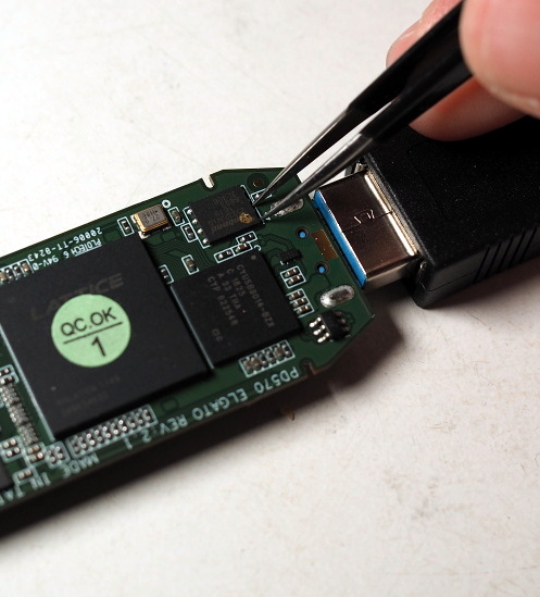
Inspired by the software fix, [Mike] wondered if there was a way he could simply force the Elgato to output video in the desire format by default. He found a firmware dump for the device online, and found where the pixel formats were referenced by searching for their names in ASCII with hexdump. Looking through the source for the Linux USB Video Class (UVC) driver, he was then able to determine what the full 16 byte sequence should be for each video mode was so he could zero out the unwanted ones. Then it was just a matter of flashing his modified firmware back to the hardware.
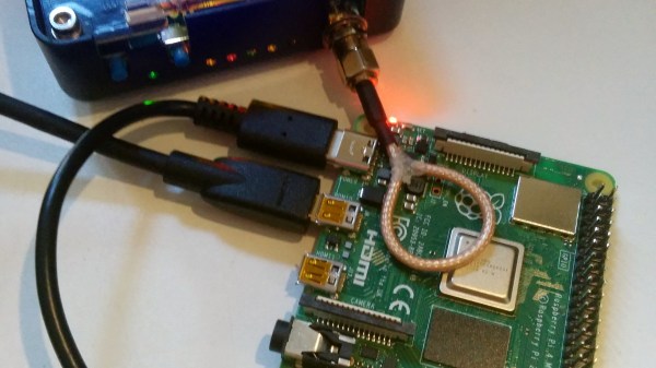
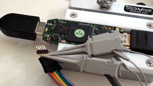
But there was a problem: with the modified firmware installed, the device stopped working. After investigating the obvious culprits, [Mike] broke out the oscilloscope and hooked it up to the Elgato’s flash chip. It turns out that due to a bug in the program he was using, the SPI erase commands weren’t getting sent during the flash. This lead to corrupted firmware which was keeping the Elgato from booting. After making a pull request with his fixes, the firmware flashed without incident and the capture device now does double-duty as a webcam when necessary.
We could certainly think of easier and quicker was to roll your own webcam, but we’re glad that [Mike] took the time to modify his Elgato Cam Link 4K and document it. It’s a fantastic example of practical firmware hacking, even if you’re not in the market for a new high-definition video conferencing rig.