Open Source High Speed SiGe IC Production For Free!

We’ve covered the Tiny Tapeout project a few times on these pages, and while getting your digital IC design out there onto actual silicon for a low cost is super cool, it is still somewhat limited. Now, along comes the German FMD QNC project funding MPW (multi-project wafer) runs not in bog standard Silicon CMOS but Silicon-Germanium bipolar technology. And this is accessible to you and me, of course, provided you have the skills to design in this high-speed analog technology.

The design can be submitted via Github by cloning the IHP-Open-DesignLib repo, adding your design, and issuing a pull request. If your submission passes the correctness checks and is selected, it will be fabricated in-house by the IHP pilot line facility, which means it will take at least four months to complete.  However, there are a few restrictions. The design must be open source, DRC complete (obviously!) and below a somewhat limiting two square millimetres. Bonus points for selecting your project can be had for good documentation and a unique quality, i.e., they shouldn’t have too many similar designs in the project archive. Also, you don’t get to keep the silicon samples, but you may rent them for up to two years for evaluation. In fact, anybody can rent them.  Still, it’s a valuable service to trial a new technique or debug a design and a great way to learn and hone a craft that is difficult to get into by traditional means. Such projects would be an excellent source of verifiable CV experience points we reckon!

If you fancy getting your hands on your own silicon, but bipolar SiGe is a bit of a stretch, look no further than our guide to Tiny Tapeout. But don’t take our word for it—listen to the creator himself!

Remote-Controlled Hypercar Slices Through Air

Almost all entry-level physics courses, and even some well into a degree program, will have the student make some assumptions in order to avoid some complex topics later on. Most commonly this is something to the effect of “ignore the effects of wind resistance” which can make an otherwise simple question in math several orders of magnitude more difficult. At some point, though, wind resistance can’t be ignored any more like when building this remote-controlled car designed for extremely high speeds.

[Indeterminate Design] has been working on this project for a while now, and it’s quite a bit beyond the design of most other RC cars we’ve seen before. The design took into account extreme aerodynamics to help the car generate not only the downforce needed to keep the tires in contact with the ground, but to keep the car stable in high-speed turns thanks to its custom 3D printed body. There is a suite of high-speed sensors on board as well which help control the vehicle including four-wheel independent torque vectoring, allowing for precise control of each wheel. During initial tests the car has demonstrated its ability to  corner at 2.6 lateral G, a 250% increase in corning speed over the same car without the aid of aerodynamics.

We’ve linked the playlist to the entire build log above, but be sure to take a look at the video linked after the break which goes into detail about the car’s aerodynamic design specifically. [Indeterminate Design] notes that it’s still very early in the car’s development, but has already exceeded the original expectations for the build. There are also some scaled-up vehicles capable of transporting people which have gone to extremes in aerodynamic design to take a look at as well.

Continue reading “Remote-Controlled Hypercar Slices Through Air”

From Nanoamps To Gigahertz: The World’s Most Extreme Op Amps

The operational amplifier, or op amp, is one of the most basic building blocks used in analog circuits. Ever since single-chip op amps were introduced in the 1960s, thousands of different types have been developed, some more successful than others. Ask an experienced analog designer to name a few op amps, and they’ll likely mention the LM324, the TL072, the NE5534, the LM358, and of course the granddaddy of all, the uA741.

If those part numbers don’t mean anything to you, all you need to know is that these are generic components that you can buy anywhere and that will do just fine in the most common applications. You can buy fancier op amps that improve on some spec or another, sometimes by orders of magnitude. But how far can you really push the concept of an operational amplifier? Today we’ll show you some op amps that go way beyond these typical “jellybean” components.

Before we start, let’s define what exactly we mean when we say “operational amplifier”. We’re looking for integrated op amps, meaning a single physical component, that have a differential high-impedance voltage input, a single-ended voltage output, DC coupling, and high gain meant to be used in a feedback configuration. We’re excluding anything made from discrete components, as well as less-general circuits like fixed-gain amplifiers and operational transconductance amplifiers (OTAs).

Continue reading “From Nanoamps To Gigahertz: The World’s Most Extreme Op Amps”

Differential Drive Doesn’t Quite Work As Expected

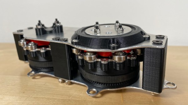
Placing two motors together in a shared drive is a simple enough task. By using something like a chain or a belt to couple them, or even placing them on the same shaft, the torque can be effectively doubled without too much hassle. But finding a way to keep the torque the same while adding the speeds of the motors, rather than the torques, is a little bit more complicated. [Levi Janssen] takes us through his prototype gearbox that attempts to do just that, although not everything works exactly as he predicts.

The prototype is based on the same principles as a differential, but reverses the direction of power flow. In something like a car, a single input from a driveshaft is sent to two output shafts that can vary in speed. In this differential drive, two input shafts at varying speeds drive a single output shaft that has a speed that is the sum of the two input speeds. Not only would this allow for higher output speeds than either of the two motors but in theory it could allow for arbitrarily fine speed control by spinning the two motors in opposite directions.

The first design uses two BLDC motors coupled to their own cycloidal drives. Each motor is placed in a housing which can rotate, and the housings are coupled to each other with a belt. This allows the secondary motor to spin the housing of the primary motor without impacting the actual speed that the primary motor is spinning. It’s all a lot to take in, but watching the video once (or twice) definitely helps to wrap one’s mind around it.

The tests of the drive didn’t go quite as planned when [Levi] got around to measuring the stall torque. It turns out that torque can’t be summed in the way he was expecting, although the drive is still able to increase the speed higher than either of the two motors. It still has some limited uses though as he notes in the video, but didn’t meet all of his expectations. It’s still an interesting build and great proof-of-concept otherwise though, and if you’re not clear on some of the design choices he made there are some other builds out there that take deep dives into cycloidal gearing or even a teardown of a standard automotive differential.

Continue reading “Differential Drive Doesn’t Quite Work As Expected”

A Nerf Gun Upgrade

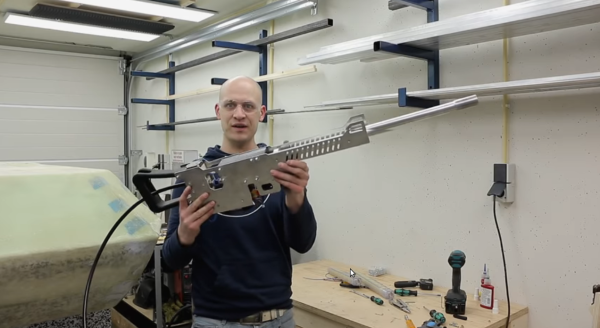
A lot of us have nostalgia for our childhood toys, and as long as they’re not something like lawn darts that nostalgia often leads to fun upgrades since some of us are adults with industrial-sized air compressors. Classics like Super Soakers and Nerf guns are especially popular targets for improvements, and this Nerf machine gun from [Emiel] is no exception.

The build takes a Nerf ball-firing toy weapon and basically tosses it all out of the window in favor of a custom Nerf ball launching rifle. He starts with the lower receiver and machines a pneumatic mechanism that both loads a ball into the chamber and then launches it. This allows the rifle to be used in both single-shot mode and also in fully-automatic mode. From there, a barrel is fashioned along with the stock and other finishing touches.

[Emiel] also uses a high-speed camera to determine the speed of his new Nerf gun but unfortunately it isn’t high-speed enough, suffering from the same fate as one of the fastest man-made objects ever made, and he only has a lower bound on the speed at 400 km/h. If you don’t want to go fast with your Nerf builds, though, perhaps you should build something enormous instead. Continue reading “A Nerf Gun Upgrade”

Visualizing How Signals Travel In A PCB

If you play with high speed design for long enough, eventually you’re going to run into clock skew and other weird effects. [Robert Feranec] recently ran into this problem and found an interesting solution to visualizing electric fields in a PCB.

A word of warning before we dig into this, for most of the projects we see on Hackaday something like this is completely superfluous. There aren’t many people dealing with high speed interfaces here, and there aren’t many people dealing with 100 Gigabit per second data links, period. That said, it’s not unheard of, and at the very least it’s interesting to look at.

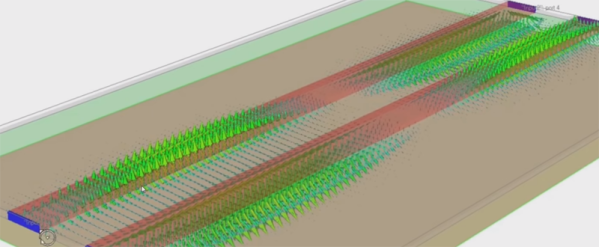
The basics of this video is simulating the signals visually in a differential pair on a (virtual) printed circuit board. The software for this is Simbeor, and [Robert] talked to the founder of the company behind this software after watching a video on simulating electric fields in differential traces. This software does what it says, and is a great illustration of why differential pairs must have the same length.

While this might not be for everyone, it is a fantastic visualization of signals in high-speed design that goes above and beyond what you would expect from a Spice simulation. Even if you’re not doing high-speed design, you may someday and it’s never too soon to get an intuitive understanding of how electrons work.

Continue reading “Visualizing How Signals Travel In A PCB”

Video: Putting High Speed PCB Design To The Test

Designing circuit boards for high speed applications requires special considerations. This you already know, but what exactly do you need to do differently from common board layout? Building on where I left off discussing impedance in 2 layer Printed Circuit Board (PCB) designs, I wanted to start talking about high speed design techniques as they relate to PCBs.  This is the world of multi-layer PCBs and where the impedance of both the Power Delivery Network (PDN) and the integrity of the signals themselves (Signal Integrity or SI) become very important factors.

I put together a few board designs to test out different situations that affect high speed signals. You’ve likely heard of vias and traces laid out at right angles having an impact. But have you considered how the glass fabric weave in the board itself impacts a design? In this video I grabbed some of my fanciest test equipment and put these design assumptions to the test. Have a look and then join me after the break for more details on what went into this!

Continue reading “Video: Putting High Speed PCB Design To The Test”