Better Simulators With Homemade Potentiometers

Perhaps you’ve played a flight simulator before, using something like a mouse and keyboard. That’s a fine experience, but like any other activity you can get a lot more out of it if you put a little more effort into the experience. Some will upgrade to a joystick for a modest improvement, and others will build incredible accurate cockpit replicas down to the smallest detail. The builders of these “pits” are always looking for ways of improving their setups, and it’s from this world that we find a method of building specialized, inexpensive hall-effect sensors.

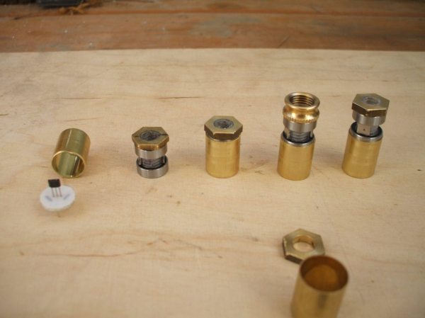
A hall-effect sensor is a circuit that outputs a voltage based on the presence of an external magnetic field. These can be used to make compasses, but with a permanent magnet in close proximity can also be used to create a potentiometer-like device at lower cost and with higher precision than a similarly-priced pot. There was a method of building these in the simulator world using the housing of a Bic pen and some strong glue, but [LocNar] has improved on this method as well. He repurposed some bearings and some stock metal tubing in order to fabricate a professional-level sensor at a fraction of the cost.

This build is essentially a solution for anyone needing a potentiometer that’s easier to build, less expensive, has higher precision, and interacts with a digital input in a much more predictable (and programmable) way. Certainly this has applications in the simulator world, but will work for many other applications. If you’ve never thought about the intricacies (and shortcomings) of potentiometers, some other folks have taken a deep dive into that as well.

Thanks to [Keith O] for the tip!

Add A Trackpoint To A Mechanical Keyboard

People love their tech, and feel like something’s missing when it’s not there. This is the story of one person’s desire to have the venerable trackpoint in their new keyboard.

[Klapse] loves a Lenovo old-style non-chicklet keyboard, so, despite the cost, five were ordered. They very quickly ended up with keys that didn’t work, although the trackpoints still did. After buying a sixth which ended up the same, [Klapse] decided that maybe giving up on the Lenovo keyboards was the best idea. A quick stop at a local store scored a fill-in mechanical keyboard, but in the back of [klapse]’s mind the need for a trackpoint remained. Maybe one could be frankensteined in to the keyboard that was just purchased?

Underside of the trackpoint, fitted to the keyboard PCB

The keyboard’s circuit board had traces everywhere, with nowhere to drill through between the correct keys, typically between the G, H and Y keys. But there was a hole used for mounting the PCB nearby. between the H, J, U and Y keys. The trackpoint needed to be extended to reach all the way through the key caps, so [klapse] searched the house looking for something that might do. Turns out that a knitting needle fits perfectly.

At this point a side-hack emerged. [Klapse] found a drill bit small enough to make the necessary hole in the trackpoint shaft to fit the needle. But the bit was too small for the drill chuck. In true hacking style, the bit was wrapped with duct tape and held in the drill. Sure, it wobbled a lot and it was really difficult to get it to drill in the center of the shaft, but it worked, eventually. The needle was cut off and glued into the hole, the key caps were modified a bit to allow the trackpoint through and the rubber tip put back on.

They say, “desire to cram old tech into new is the mother of invention.” Or something similar, anyway. Check out how a Teensy liberated a Lenovo laptop keyboard trackpoint and all. Also, check out this custom keyboard with integrated trackpoint, of course.

Motion-Controlled KVM Switch

Once upon a time, [hardwarecoder] acquired a Gen8 HP microserver that he began to toy around with. It started with ‘trying out’ some visualization before spiraling off the rails and fully setting up FreeBSD with ZFS as a QEMU-KVM virtual machine. While wondering what to do next, he happened to be lamenting how he couldn’t also fit his laptop on his desk, so he built himself a slick, motion-sensing KVM switch to solve his space problem.

At its heart, this device injects DCC code via the I2C pins on his monitors’ VGA cables to swap inputs while a relay ‘replugs’ the keyboard and mouse from the server to the laptop — and vice-versa — at the same time. On the completely custom PCB are a pair of infrared diodes and a receiver that detects Jedi-like hand waves which activate the swap. It’s a little more complex than some methods, but arguably much cooler.

Using an adapter, the pcb plugs into his keyboard, and the monitor data connections and keyboard/mouse output to the laptop and server stream out from there. There is a slight potential issue with cables torquing on the PCB, but with it being so conveniently close, [hardwarecoder] doesn’t need to handle it much.

Continue reading “Motion-Controlled KVM Switch”

Making VR A Little More Usable With A Pinch Gesture Ring

[Florian] wants to browse the web like an internet cowboy from a cyberpunk novel. Unfortunately, VR controllers are great for games but really incapacitate a hand for typing. A new input method was needed, one that would free his fingers for typing, but still give his hands detailed input into the virtual world.

Since VR goggles have… hopefully… already reached peak ridiculousness, his first idea was to glue a Leap Motion controller to the front of it. It couldn’t look any sillier after all.  The Leap controller was designed to track hands, and when combined with the IMU built into the VR contraption, did a pretty good job of putting his hands into the world. Unfortunately, the primary gesture used for a “click” was only registering 80% of the time.

The gesture in question is a pinching motion, pushing the thumb and middle finger together. He couldn’t involve a big button without incapacitating his hands for typing. It took a few iterations, but he arrived at a compact ring design with a momentary switch on it. This is connected to an Arduino on his wrist, but was out of the way enough to allow him to type.

It’s yet another development marching us to usable VR. We personally can’t wait until we can use some technology straight out of  Stephenson or Gibson novel.

Two Pins For The Price Of One

One of the most common problems in the world of microcontrollers is running out of resources. Sometimes it’s memory, where the code must be pared down to fit into the flash on the microcontroller. Other times, as [Fabien] found out when he ran out of pins, the limitations are entirely physical. Not one to give up, he managed to solve the problem by using one pin for two tasks. (Google Translate from French)
During a recent project, [Fabien] realized he had forgotten to add a piezo buzzer to his project. All of the other pins were in use, though, so his goal was to use one of the input pins to handle button presses but to occasionally switch to output mode when the piezo buzzer was needed. After all, the button is only used at certain times, and the microcontroller pin sits unused otherwise. After a few trials, he has a working solution that manages to neither burn out itself nor the components in the circuit, and none of the components interfere with the other’s normal operation.
While it isn’t the most technically advanced thing we’ve ever seen here, it is a great example of using the tools at your disposal to elegantly solve a problem. More than that, though, it’s a thorough look into the details of pull-up and pull-down resistors, how microcontrollers see voltage as logic levels, and how other pieces of hardware interact with microcontrollers of all different types. This is definitely worth a read, especially if you are a beginner in this world.

AVR External Memory Interface (XMEM) Reads Input Matrix

Reading from a large number of inputs, like this piano keyboard, can be tedious. Even when multiplexing there’s a lot to keep track of. But if you choose the right microcontroller, you may have hardware assistance. Here’s an ATmega640 is using it’s external memory interface to read the key matrix.

You may remember the Open Music Labs article about reading from a shift register using just one pin of a microcontroller. This time around a shift register is still used, but instead of pulling in a long line of parallel inputs, the switches are multiplexed to reduce the number of I/O pins used to read them.

A 74HC573 is used to facilitate the multiplexing. We won’t go into how that part is accomplished; there’s a separate post that explains the process. What’s unique here is that the XMEM peripheral of the AVR microcontroller is used to grab the data. This is intended for external memory chips, but if you get the timing just right, it greatly simplifies reading in a matrix of up to 128 inputs.

Reading Inputs From Shift Registers Using Just One Single Pin

Here’s an interesting article about reading data from shift registers using less than three pins. 74HC165 shift registers are a popular choice for adding inputs to a microcontroller. They have a parallel input register which can be read using the latch, then shifted into a microcontroller via the data and clock pins. For those counting, that’s the three pins normally associated with driving these devices.

This hack first does away with the latch pin. The addition of a carefully trimmed RC circuit (capacitor is charged by the clock pin, then the resistor lets that cap slowly discharge) means that the device will not latch until after the clock stops toggling. This technique drops the control down to just two pins (data and clock). You can still use hardware SPI to read the data using this method. It’s the same as using SPI to drive 595 shift registers except the microcontroller reads data instead of writing it.

But wait, there’s more! The diagram above actually shows a way of reading this shift register with just one pin. Notice that the clock and data pins are now connected to just one of the microcontroller pins. The data pin has an added resistor, which keeps the current low enough that it will not compete with the clock signal coming from the microcontroller. In between clock pulses, the microcontroller switches from output to input to read the data pin on each cycle. Give it a try, it’s a fun experiment!