Slit lamps are prohibitively expensive in the third world areas of India where they are most needed. An invention that’s been around for over a hundred years, the slit lamp is a simple-in-concept way to see and diagnose a large array of ocular issues.
Since they are relatively old by technological standards, the principles behind them have become more and more understood as time has gone on. While a nice lab version with a corneal microscope is certainly better, innovations in manufacturing have brought the theoretical minimum cost of the device way down, or at least that’s what [Kewal Chand Swami] hopes.
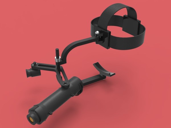
His design aims for portability and cost reduction. It must be able to travel to remote locations and it must be significantly cheaper than the lab versions. It uses off-the-shelf lenses in a 3D printed housing with a simple LED torch, the kind you can buy for a dollar at the check-out stand.
The assembly slides onto the user’s head and is held there with straps. The doctor can adjust where the slit the lamp shines and also look through a microscope to diagnose the issue. Hopefully devices like this will see similar community support to the prosthetic projects we’ve covered.