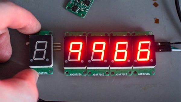
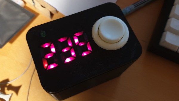
Beautiful Moving Origami Light Made From Scrap

Whenever [MakerMan] hits our tip line with one of his creations, we know it’s going to be something special. His projects are almost exclusively built using scrap and salvaged components, and really serve as a reminder of what’s possible if you’re willing to open your mind a bit. Whether done out of thrift or necessity, he proves the old adage that one man’s trash is often another’s treasure.

We’ve come to expect mainly practical builds from [MakerMan], so the beautiful ceiling light which he refers to as a “Kinetic Chandelier”, is something of a change of pace. The computer controlled light is able to fold itself up like an umbrella while delivering a pleasing diffuse LED glow. He tells us it’s a prototype he’s building on commission for a client, and we’re going to go out on a limb and say he’s going to have a very satisfied customer with this one.

Like all of his builds, the Kinetic Chandelier is almost entirely built out of repurposed components. The support rods are rusty and bent when he found them, but after cutting them down to size and hitting them with a coat of spray paint you’d never suspect they weren’t purpose-made. The light’s “hub” is cut out of a chunk of steel with an angle grinder, and uses bits of bike chain for a flexible linkage.

Perhaps most impressive is his DIY capstan which is used to raise and lower the center of the light. [MakerMan] turns down an aluminum pulley on a lathe to fit the beefy gear motor, and then pairs that with a few idler pulleys held in place with bits of rebar welded together. It looks like something out of Mad Max, but it gets the job done.

Finally, he salvages the LED panels out of a couple of cheap work lights and welds up some more rebar to mount them to the capstan at the appropriate angle. This gives the light an impressive internal glow without a clear source when viewed from below, and really gives it an otherworldly appearance.

This isn’t the first time we’ve seen a hacker put together their own chandelier, or even the first time we’ve seen it done with scrap parts. But what [MakerMan] has put together here may well be the most objectively attractive one we’ve seen so far.

Continue reading “Beautiful Moving Origami Light Made From Scrap”

Flywire Circuits At The Next Level

The technique of assembling circuits without substrate goes by many names; you may know it as flywiring, deadbugging, point to point wiring, or freeform circuits. Sometimes this technique is used for practical purposes like fixing design errors post-production or escaping tiny BGA components (ok, that one might be more cool than practical). Perhaps our favorite use is to create art, and [Mohit Bhoite] is an absolute genius of the form. He’s so prolific that it’s difficult to point to a particular one of his projects as an exemplar, though he has a dusty blog we might recommend digging through [Mohit]’s Twitter feed and marveling at the intricate works of LEDs and precision-bent brass he produces with impressive regularity.

So where to begin? Very recently [Mohit] put together a small wheeled vehicle for persistence of vision drawing (see photo above). We’re pretty excited to see some more photos and videos he takes as this adorable little guy gets some use! Going a little farther back in time there’s this microcontroller-free LED scroller cube which does a great job showing off his usual level of fit and finish (detail here). If you prefer more LEDs there’s also this hexagonal display he whipped up. Or another little creature with seven segment displays for eyes. Got those? That covers (most) of his last month of work. You may be starting to get a sense of the quality and quantity on offer here.

We’ve covered other examples of similar flywired circuits before. Here’s one of [Mohit]’s from a few years ago. And another on an exquisite headphone amp encased in a block of resin. What about a high voltage Nixie clock that’s all exposed? And check out a video of the little persistence of vision ‘bot after the break.

Thanks [Robot] for reminding us that we hadn’t paid enough attention to [Mohit]’s wonderful work!

Continue reading “Flywire Circuits At The Next Level”

The (UV) Writing’s On The Wall

[Michael Karliner]’s Belshazzar, named for the Biblical character upon whose wall the writing appeared, is a unique light painting machine, that tracks an array of UV LEDs across a glow-in-the-dark background to paint transient dot-matrix letters in light. It was one of many cyberpunk-themed art pieces in Null Sector at the 2018 Electromagnetic Field hacker camp this summer.

The row of LEDs hangs down from a carriage that traverses a tubular rail, and is edged forward by means of a stepper motor driving a roller. This arrangement delivers the benefit that it can be scaled for displays of any length. The LEDs are driven from an Arduino via a Texas Instruments TLC5940 PWM driver ship.The result can be seen in the video below the break, and those who saw it at EMF may remember it tracing suitably dystopian phrases.

Continue reading “The (UV) Writing’s On The Wall”

Analog Clock Goes Digital, Or Vice Versa

Designing a good clock takes a lot of considerations. It’s not just hands, faces, and numbers anymore; there are also word clocks, electronic clocks, marble clocks, or water clocks, and just about anything else imaginable can be used to tell time. Of course, electronic clocks are great for their versatility, and this one shows off an analog-looking clock that is (of course) digital, leveraging all of the perks of analog with all of the upsides of digital electronics.

One of the key design considerations that [Sasa] had while building this piece was that it needed to be silent. LEDs certainly fit that description, so the decision was made to go with an WS2812b ring. It runs using a STM ST32F103 Nucleo board (and a cheaper version of it in later versions of this clock) which shows a red LED for the current hour, yellow LEDs for the traditional analog clock divisions, a green LED for the current minute, and glows the rest of the LEDs up to the current minute with a rainbow pattern.

This is a really clean, simple build with good design at its core, and would be easy to replicate if you’re looking for an eye-catching clock to build. As a bonus, all of the schematics and code are available on the project site, so everything you need is there. If you’re looking for more inspiration, there are some clocks that are even more unique, like this marble clock that is a work of art — but is anything but silent.

A Daylight-Readable Bar Graph Display In The 70s Wasn’t Cheap

The driver board with display attached; the row of lamps is visible on the right hand side.

LEDs weren’t always an easy solution to displays and indicators. The fine folks at [Industrial Alchemy] shared pictures of a device that shows what kind of effort and cost went into making a high brightness bar graph display in the 70s, back when LEDs were both expensive and not particularly bright. There are no strange materials or methods involved in making the display daylight-readable, but it’s a peek at how solving problems we take for granted today sometimes took a lot of expense and effort.

The display is a row of 28 small incandescent bulbs, mounted in a PCB and housed in a machined aluminum frame. Holes through which to view the bulbs are on both the top and front of the metal housing, which allows the unit to be mounted in different orientations. It was made as a swappable module, its 56 machined gold pins mate to sockets on the driver board. The driver board itself consists of 14 LM119 dual comparators, each of which controls two bulbs on the display.

An example of a Wamco minitron bar graph display. Each window contains an incandescent filament. [Source: industrialalchemy.org]
[Industrial Alchemy] believes that the display unit itself may have been a bit of a hack in its own way. Based on the pin spacing and dimensions of the driver board, they feel that it was probably designed to host a row of modular units known as the Wamco minitron bar graph display. An example is pictured here; they resembled DIP chips and could be stacked side-by-side to make a display of any length. Each window contained an incandescent filament in a reflective well, and each light could be individually controlled.

These minitron bar graph units could only be viewed from the top, and were apparently high in cost and low in availability. Getting around these limitations may have been worth creating this compatible unit despite the work involved.

Display technology has taken many different turns over the years, and you can see examples of many of them in one place in the Circus Clock, which tells the time with a different technology for each digit: a nixie, a numitron, a 7-segment thyratron tube, a VFD, an LED dot display, and a rear projection display.

The Portable, Digital, Visual Theremin

The theremin is, for some reason, what people think of first when they think of electronic musical instruments. Maybe that’s because it was arguably the first purely electronic musical instrument, or because there’s no mechanical analog to something that makes sound simply by waving your hand over it. This project takes that idea and cranks it up to eleven. It’s a portable synthesizer that’s controlled by IR reflectors. Just wave your hand in front of it, and that’s what pitch is going to sound.

The audio hardware for this synth is, like so many winners in the Musical Instrument Challenge in this year’s Hackaday Prize, based on the Teensy and its incredible Audio library. The code consists of two oscillators and a pink noise generator. Pressing down button one activates the oscillators, and the frequency is determined by the IR sensor. Button two cycles through various waveforms, while the third and fourth buttons shift the octaves up and down. The output is I2S, and from there everything is out to an amplifier and speaker.

Of course, it’s really not a musical instrument unless it looks cool, and that’s where this project is really great. It’s a fully 3D printed enclosure that actually looks good. There’s an 8×8 LED array to display the current waveform, and this is something that could actually be a product instead of a project. It’s a great synth, and we’re happy to have it in the running for the Hackaday Prize.

Continue reading “The Portable, Digital, Visual Theremin”

Lessons In Disposable Design From A Cheap Blinky Ball

Planned obsolescence, as annoying as it is when you’re its victim, still has to be admired. You can’t help but stand in awe of the designer who somehow managed to optimize a product to live one day longer than its warranty period. Seriously, why is it always the next day?

The design of products that are never intended to live long enough to go obsolete must be similarly challenging, and [electronupdate] did a teardown of a cheap LED blinky toy to see what’s involved. You’ve no doubt seen these seizure-triggering silicone balls before, mostly at checkout counters and the like where they’re sold at prices many hundreds of times what it took to make them. This particular device, which seems representative of the species, has two bright LEDs, a small controller chip, a trio of button cells for power, and a springy switch to activate it. All this is mounted to a cheap scrap of phenolic resin PCB, with the controller chip and one of the LEDs covered by a blob of clear epoxy.

This teardown one-ups most others, as [electronupdate] disrobes the chip and points a microscope at the die; the video below shows just how few transistors are employed and proposes a likely circuit. Everything about this ball just oozes cheapness, and it’s likely these things cost essentially nothing to build. Which makes sense for something destined for the landfill within a week or so.

Yes, this annoying blinky-thing is low-end garbage, but there are still design lessons to be learned from it. Anything that’s built for a broad market has to be built to a price point, and understanding those constraints is important to understanding how planned obsolescence works.

Continue reading “Lessons In Disposable Design From A Cheap Blinky Ball”