We love it when something common gets put to a new and unusual use, especially when it’s one of those, “Why didn’t I think of that?” situations. This digital clock with a suspended display is just such a thing.
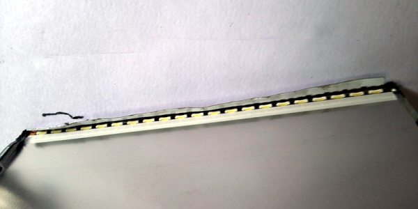
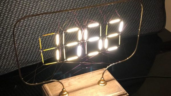
The common items in this case were “filaments” from LED light bulbs, those meant to mimic the look of clear-glass incandescent light bulbs. [Andypugh] had been looking at them with interest for a while, and realized they were perfect as the segments for a large digital clock. The frame of the clock was formed from bent brass U-channel and mounted to an oak base via turned stanchions. The seven-segment displays were laid out in the frame and the common anodes of the LED filaments were connected together, with the cathode for each connected to a very fine wire. Each wire was directed through a random hole in the frame and channeled down into the base, to be hooked to one of the four DS8880 VFD driver chips. The anode wires form a lacy filigree behind the segments, which catch the light and make then look a little like a spider’s web. It looks great, but nicht für der gefingerpoken – the frame is at 80 VDC to drive the LED segments. The clock is synced to the UK atomic clock with a 60-kHz radio link; see the long, painful sync process in the video below.
We like the open frame look, which we’ve seen before with an equally dangerous sculptural nixie clock. And this gives us some ideas for what to do with those filament LEDs other than turning them back into a light bulb. And if [Andy] sounds familiar, it could be because he’s appeared here before. First of all resurrecting the parts bin for an entire classic motorcycle marque, and then as the designer of SMIDSY, a robot competitor in the first incarnation of the UK Robot Wars series.
Continue reading “Old LED Light Bulbs Give Up Filaments For Spider Web Clock”