Simple Quadcopter Testbed Clears The Air For Easy Algorithm Development

We don’t have to tell you that drones are all the rage. But while new commercial models are being released all the time, and new parts get released for the makers, the basic technology used in the hardware hasn’t changed in the last few years. Sure, we’ve added more sensors, increased computing power, and improved the efficiency, but the key developments come in the software: you only have to look at the latest models on the market, or the frequency of Git commits to Betaflight, Butterflight, Cleanflight, etc.

With this in mind, for a Hackaday prize entry [int-smart] is working on a quadcopter testbed for developing algorithms, specifically localization and mapping. The aim of the project is to eventually make it as easy as possible to get off the ground and start writing code, as well as to integrate mapping algorithms with Ardupilot through ROS.

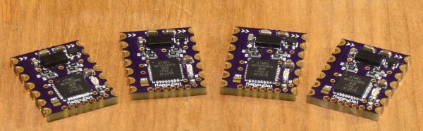
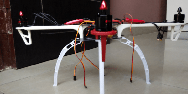
The initial idea was to use a Beaglebone Blue and some cheap hobby hardware which is fairly standard for a drone of this size: 1250 kv motors and SimonK ESCs, mounted on an f450 flame wheel style frame. However, it looks like an off-the-shelf solution might be even simpler if it can be made to work with ROS. A Scanse Sweep LIDAR sensor provides point cloud data, which is then munched with some Iterative Closest Point (ICP) processing. If you like math then it’s definitely worth reading the project logs, as some of the algorithms are explained there.

It might be fun to add FPV to this system to see how the mapping algorithms are performing from the perspective of the drone. And just because it’s awesome. FPV is also a fertile area for hacking: we particularly love this FPV tracker which rotates itself to get the best signal, and this 3D FPV setup using two cameras.

Robot Radar Module

For his Hackaday Prize entry, [Ted Yapo] is building a Robot Radar Module breakout board. His design uses the A111 60 GHz pulsed coherent radar (PCR) sensor from Acconeer AB (New Part alert!) .

The A111 is a low power, high precision sensor ideal for use in object detection or gesture sensing applications. The BGA package is tiny – 5.5 mm x 5.2 mm, but it does not appear very difficult for a hacker to assemble. The sensor includes an integrated baseband, RF front-end and Antenna in Package so you don’t have to mess with RF layout headaches. Acconeer claims the sensor performance is not affected with interference from noise, dust, color and direct or indirect light. Sensing range is about 2 m with a +/- 2 mm accuracy. And at just under $10 a pop for 10 units or more, it would make a nice addition to augment the sensor package on a Robot.

To get started, [Ted] is keeping his design simple and small – the break out board measures just 32 mm x 32 mm. The radar sensor itself doesn’t require any parts other than a crystal and its loading capacitors. A LDO takes care of the 1.8 V required by the A111. Three 74LVC2T45 chips translate the SPI digital interface from 1.8 V to external logic levels between 1.8 V to 5 V. The three level translation chips could possible be replaced by a single six or eight channel translator – such as one from the TXB series from TI. For his first PCB iteration, [Ted] is expecting to run in to some layout or performance issues, so if you have any feedback to give him on his design, check out his hardware repository on Github.

Acconeer provides a Getting Started guide for their Evaluation Kits, which includes a detailed Raspberry-Pi / Raspbian installation and an accompanying video (embedded after the break) targeted at hackers. We are eagerly looking forward to the progress that [Ted] makes with this sensor breakout. Combined with LiDAR ToF sensor breakout boards, such as the MappyDot, it would be a great addition to your robot’s sensing capabilities.

Continue reading “Robot Radar Module”

Litar: LiDAR air guitar

Litar: An Air Guitar Using LiDAR

This year, [Blecky’s] Hackaday Prize Entry is an air guitar which uses multiple LiDAR sensors to create the virtual strings. What’s also neat is that he’s using his own LiDAR sensor, the MappyDot Plus, an enhanced version of his 2017 Prize Entry, the MappyDot.

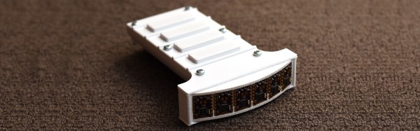
He uses a very clever arrangement of six sensors to get four virtual strings. Each sensor scans a 25-degree field of view. Three adjacent sensors are used to define a string, with the string being in the overlap of the outer two of those sensors. The middle sensor is used for the distance data.

For the chords, he started out using some commercially made joysticks but ran into some ergonomic issues. Also, the manufacturer was discontinuing the product, a no-no for an open source project. So he abandoned that approach and designed his own buttons. He came up with a PCB with a linear hall effect sensor and some springs on it. The button has a magnet attached to its underside and sits on the springs. That way he gets the press and can do vibrato as well.

He plans to use Bluetooth MIDI so that you can play the sound on a phone or laptop but for now he lights up an LED beside each sensor as you press the strings.

Debunking Moon Landing Denial With An Arduino And Science

It’s sad that nearly half a century after the achievements of the Apollo program we’re still arguing with a certain subset of people who insist it never happened. Poring through the historical record looking for evidence that proves the missions couldn’t possibly have occurred has become a sad little cottage industry, and debunking the deniers is a distasteful but necessary ongoing effort.

One particularly desperate denier theory holds that fully spacesuited astronauts could never have exited the tiny hatch of the Lunar Excursion Module (LEM). [AstronomyLive] fought back at this tendentious claim in a clever way — with a DIY LIDAR scanner to measure Apollo artifacts in museums. The hardware is straightforward, with a Garmin LIDAR-Lite V3 scanner mounted on a couple of servos to make a quick pan-tilt head. The rig has a decidedly compliant look to it, with the sensor flopping around a bit as the servos move. But for the purpose, it seems perfectly fine.

[AstronomyLive] took the scanner to two separate museum exhibits, one to scan a LEM hatch and one to scan the suit Gene Cernan, the last man to stand on the Moon so far, wore while training for Apollo 17. With the LEM flying from the rafters, the scanner was somewhat stretching its abilities, so the point clouds he captured were a little on the low-res side. But in the end, a virtual Cernan was able to transition through the virtual LEM hatch, as expected.

Sadly, such evidence will only ever be convincing to those who need no convincing; the willfully ignorant will always find ways to justify their position. So let’s just celebrate the achievements of Apollo.

Continue reading “Debunking Moon Landing Denial With An Arduino And Science”

34C3: The First Day Is A Doozy

It’s 5 pm, the sun is slowly setting on the Leipzig conference center, and although we’re only halfway through the first day, there’s a ton that you should see. We’ll report some more on the culture of the con later — for now here’s just the hacks. Continue reading “34C3: The First Day Is A Doozy”

Hackaday Prize Entry: MappyDot, A Micro Smart LiDAR Sensor

[Blecky]’s entry to the Hackaday Prize is MappyDot, a tiny board less than a square inch in size that holds a VL53L0X time-of-flight distance sensor and can measure distances of up to 2 meters.

MappyDot is more than just a breakout board; the ATMega328PB microcontroller on each PCB provides filtering, an easy to use  I2C interface, and automatically handles up to 112 boards connected in a bus. The idea is that one or a few MappyDots can be used by themselves, but managing a large number is just as easy. By dotting a device with multiple MappyDots pointing in different directions, a device could combine the readings to gain a LiDAR-like understanding of its physical environment. Its big numbers of MappyDots [Blecky] is going for, too: he just received a few panels of bare PCBs that he’ll soon be laboriously populating. The good news is, there aren’t that many components on each board.

It’s great to see open sourced projects and tools in which it is clear some thought has gone into making them flexible and easy to use. This means they are easier to incorporate into other work and helps make them a great contestant for the Hackaday Prize.