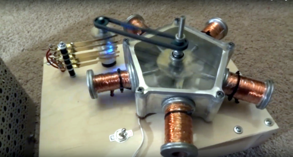
Miniature Cannon Packs A Punch, Shows Off Manual Machining Skills

CNC machine tools are getting ever more affordable for the amateur machinist, and they’re an enabling technology for many projects. But you’ve got to respect the old school approach to turning hunks of metal into finished parts with no computer control. [Ticktock34] shows off his skills on a WWII vintage manual lathe with a photo album of his .75 caliber miniature black powder cannon build. What starts as a 3″ diameter actuator from a front end loader ends up as a beautiful replica of a full-sized cannon, along with a half-filled barrel of nicely blued scrap metal. Particularly impressive is the nicely proportioned ball end, cut by hand with no more instrumentation than a set of calipers. [Ticktock34] also shares a few tips for getting the trunnions exactly squared and aligned.

Good looking, and functional – stay tuned after the break for a video with the impressive blast from a test firing – with only a quarter charge of powder, mind you.

Want something a little safer for the kiddies and less likely to result in a visit from the police? Perhaps this PVC pirate cannon is more your speed.

Continue reading “Miniature Cannon Packs A Punch, Shows Off Manual Machining Skills”

Machine Metal With Electricity: An EDM Attachment For 3D Printers

[SuperUnknown] has revealed a secret project he’s been working on. He’s cooked up an EDM attachment for 3D printers, or any CNC machine for that matter. Electrical Discharge Machining (EDM) is a method of using sparks to machine metal. EDM isn’t a new technology, in fact commercial machines have been around since the 1960’s. If you’ve ever had an arc scar up your multimeter probes, you’ve unwittingly done a bit of EDM.

The theory behind EDM is simple: High voltage between the tool and workpiece causes sparks to jump between them. Each spark erodes the workpiece (and the tool). Big EDM machines perform their magic in a liquid which acts as both a dielectric and a flushing medium. This liquid can be anything from deionzed tap water to specially formulated oil. [SuperUnknown] is using good old-fashioned tap water.

edm-rough
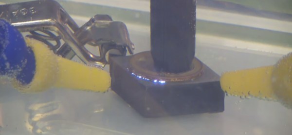
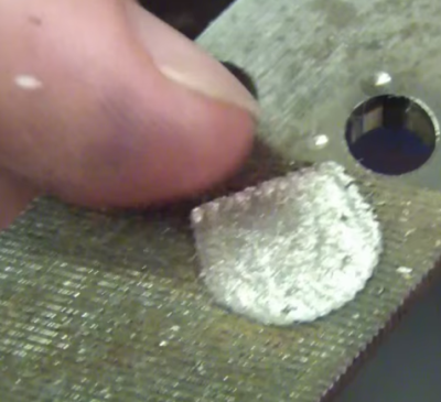
As you can imagine, a single spark won’t erode much metal. EDM machines fire tens of thousands of times per second. The exact frequencies, voltages, and currents are secrets the machine manufacturers keep close to their chests. [SuperUnknown] is zeroing in on 65 volts at 2 amps, running at 35 kHz. He’s made some great progress, gouging into hardened files, removing broken taps from brass, and even eroding the impression of a coin in steel.

While we’d love to say this is a free open source project, [superUnknown] needs to pay the bills. He’s going with crowdsourced funding. No, not another Kickstarter. This project is taking a different route. The videos of the machine will be uploaded to YouTube and visible to [superUnknown’s] Patreon supporters. They will also be available for rent using YouTube’s new rental system. [SuperUnknown] has pledged to figure out a way to make the content available for starving college students and others with limited incomes.

Based upon his previous adventures with lil’ screwy, his homemade 100 ton press, and various other projects on the Arduino verses Evil YouTube channel, we think [superUnkown] has a pretty good chance of making home EDM work. Click past the break to see two videos of the 3D printer EDM toolhead in action. We should mention that [SuperUnknown] is rather colorful with his dialogue, so make sure you’re using headphones if you’re at work.

Continue reading “Machine Metal With Electricity: An EDM Attachment For 3D Printers”

Anodized aluminium phone mount for a bike

Anodized Phone Mount For Your Bike

There’s a slew of apps out there for tracking your bike rides. If you want to monitor your ride while using the app, you’ll need it securely affixed to your bike. That’s where [Gord]’s No Dropped Calls build comes in. This aluminium mount was hand milled and anodized, which gives it a professional finish.

The mount consists of 3 parts which were machined out of stock 6061 aluminium. The plans were dreamt up in [Gord]’s head, and not drawn out, but the build log gives a good summary of the process. By milling away all of the unnecessary material, the weight of the mount was minimized.

Once the aluminium parts were finished, they were anodized. Anodization is a process that accelerates the oxidization of aluminum, creating a protective layer of aluminium oxide. [Greg] does this with a bucket of sulphuric acid and a power supply. Once the anodization is complete, the part is dyed for coloring. If you’re interested, [Gord] has a detailed writeup on home anodization.

The final product looks great, puts the phone within reach while biking, and prevents phone damage due to “dropped calls.”

Pen Gun

Pneumatic Pen Gun Is Fit For James Bond

The James Bond franchise is well-known for many things, but perhaps most important to us hackers are the gadgets. Bond always had an awesome gadget that somehow was exactly the thing he needed to get out of a jam. [hw97karbine’s] latest project would fit right into an old Bond flick. He’s managed to build a single-shot pellet gun that looks like a pen.

[hw97karbine] started out by cutting the body from a tube of carbon fiber. He used a hacksaw to do the cutting, and then cleaned up the edges on a lathe. A barrel was cut from a piece of brass tubing with a smaller diameter. These two tubes will eventually sit one inside of the other. A custom front end cap was machined from brass. One end is ribbed and glued into the carbon fiber tube. The barrel is also glued to this end of the front cap, though it’s glued to the inside of the cap. The other end of the cap has 1/8″ BSP threads cut into it in order to allow for attachments.

A rear end cap is machined from Delrin. This piece also has a Delrin piston placed inside. The piston has a small piece of rubber used as a gasket. This piston valve is what allows the gun to operate. The rear cap gets glued into place and attached to a Schrader valve, removed from an automotive tire valve stem.

To pressurize the system, a bicycle pump is attached to the Schrader valve. This pushes the piston up against the barrel, preventing any of the air from escaping. The piston doesn’t make a perfect seal, so air leaks around it and pressurizes the carbon fiber tube. The Schrader valve prevents the air from leaking out of the pen body. A special machined button was threaded onto the Schrader valve. When the button is pressed, the air escapes; the sudden pressure imbalance causes the piston to shoot backwards, opening up a path for the air to escape through the barrel. This escaping air launches the projectile. The whole process is explained better with an animation.

Now, the question left in our mind: is this the same pressure imbalance concept that was used in that vacuum pressure bazooka we saw a couple years back?

Continue reading “Pneumatic Pen Gun Is Fit For James Bond”

Machining A Skeleton Clock In 10,000 Easy Steps

Another day, another interesting YouTube channel. [Chris]’ Clickspring channel and blog is something you don’t really see much these days: machining parts with a lathe, a mill, and no CNC. The project [Chris] is working on now is a clock based on a design by [John Wilding]. It’s very large, and all the parts are constructed out of raw brass and steel stock.

Of course making a clock isn’t just about cutting out some parts on a lathe and turning them on a mill. No, you’re going to need to make the parts to make those parts. [Chris] has already made a tailstock die holder for his lathe, a clamping tool to drill holes in rods, and a beautiful lathe carrier to hold small parts.

All of this is top-notch work, with custom tin lapping tools to put a mirror finish on the parts, and far more effort than should be necessary going into absolute perfection. The clock project is turning out great, although there are several more months until it will tick its first second.

Selected videos below.

Continue reading “Machining A Skeleton Clock In 10,000 Easy Steps”

Machining A Yo-Yo With Speed Holes

A while ago, [Gord] received a notice from his daughter’s school looking for silent auction donations for a fundraiser. It’s pretty much a bake sale, only [Gord] gets to build something. He has a pretty nice machine shop, and eventually settled on building a pair of beautiful vacillating vertical pendulums. They’re yo-yos, in case you were wondering what that meant.

Each half is cut out of a 2.5″, with both sides of each half faced off and tapped. From there, eighteen speed holes shave off 22 grams of weight. The sides of the yo-yo are shaved down to a thickness of half an inch, a 14° bevel is put on each face, the edges are chamfered at 30°, and everything is polished up.

Sending a bare metal yo-yo to a raffle is apparently a little uncouth, so [Gord] anodized each half of the yo-yos in a bath of sulfuric acid, then applied dye to the surface. With everything assembled, a fancy glass and metal case was constructed and a certificate of authenticity printed out. It’s a brilliant final touch to a great project, we just wish we knew how the yo-yo performed.

Thanks [Chris] for sending this in.

Lathe Tach

Excuse Me, Sir. Do You Know How Fast Your Lathe Was Traveling Back There?

When machining metal, it is important to know how fast the cutting tool is traveling in relation to the surface of the part being machined. This amount is called the ‘Surface Speed’. There are Surface Speed standards for cutting different types of materials and it is good practice to stick with those standards in order to end up with a good surface finish as well as maximizing tool life. On a lathe, for example, having a known target Surface Speed in mind as well as a part finish diameter, it is possible to calculate the necessary spindle speed.

Hobbyist [Paul] wanted a method of measuring his lathe’s spindle speed. Since spindle speed is measured in RPM, it made complete sense to install a tachometer. After browsing eBay for a bit he found one for about $20. His purchase came with the numeric LED display, a mounting bezel and the all important hall effect sensor. The Hall effect sensor measures changes in a magnetic field and in turn varies its output voltage. [Paul] fabbed up an aluminum bracket that supports the sensor just off of the rear of the lathe spindle. A magnet was then glued to the outside diameter of the spindle below the sensor. The once per revolution signal is generated every time the magnet passes the sensor while the lathe is running. The display was mounted to the lathe near eye height by means of another aluminum bracket and case.

After a little work, [Paul] can now keep a close eye on his spindle speed with a quick glance over at his new tachometer display while he’s turning those perfect parts! If this project tickles your fancy, you may want to check out this fantastic DIY tachometer or this one that uses a soundcard.