3D-Printer Gets Hot-Swappable Hot-Ends

3D printers can be hacked into a multitude of useful machines, simply by replacing the filament extruder with a new attachment such as a laser engraver or plotter.

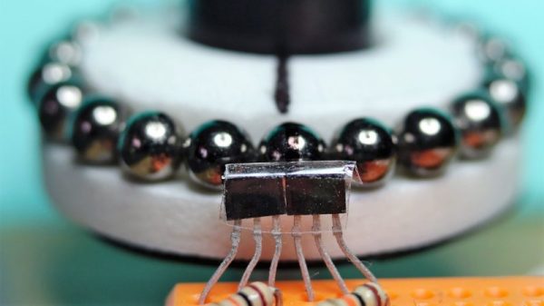
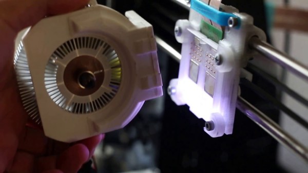
However, [geggo] was fed up with re-wiring and mounting the printhead/tool every time he wanted to try something new, and set out to design a modular printhead system for next-level convenience. The result? A magnetic base-plate, allowing a 3D printer to become a laser engraver within a matter of seconds. This new base-plate mounts onto the existing ball bearings and provides a sturdy place for attachments to snap to – with room for two at once.

Using neodymium magnets to mount the printhead to the base-plate provides enough force to keep the attachment in place and compress 30 pogo pins, which make the electrical connections. These carry the lines which are common to all attachments (heater, thermistor and fan), as well as custom connections for certain attachments – for example the extruder stepper motors.  A Flexible Flat Cable (FFC) is used to connect the pogo pin PCB to the main controller.

So far, the list of tools available for fitting includes an MK8 extruder, a E3D v6 hotend (for Bowden extrusion), a laser, a micrometer dial indicator, and a pen plotter (used for writing a batch of wedding invitations!). There was even some success milling wood.

For some automated extruder switching action we’ve shown you in the past, check out the 3d-printer tool changer.

Continue reading “3D-Printer Gets Hot-Swappable Hot-Ends”

You’ve Never Seen A Flipping Eyeball Like This One!

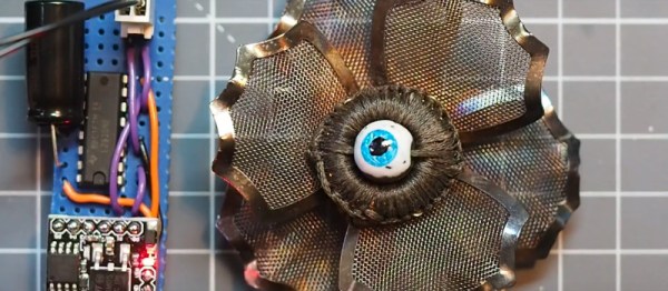
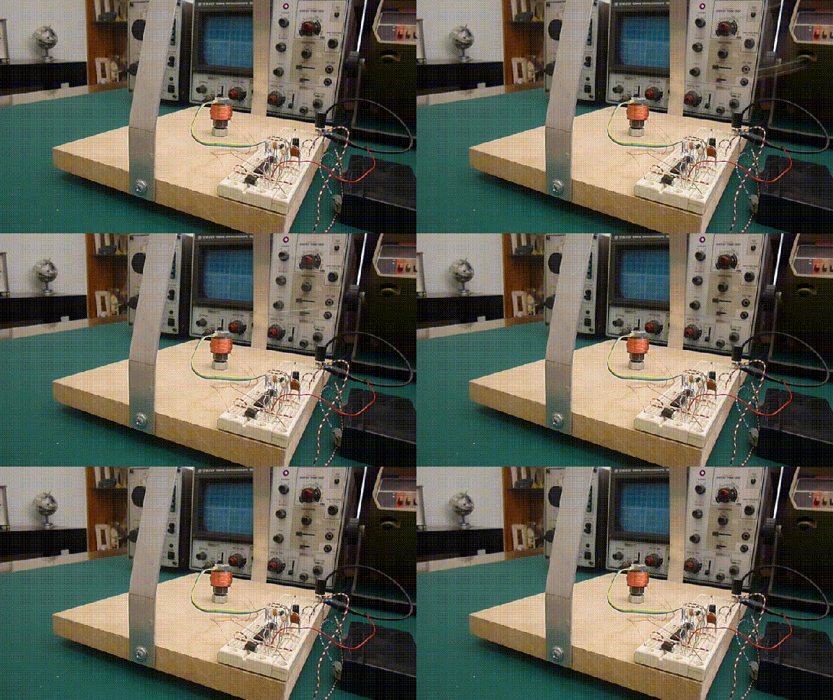
Inspired by some impressive work on textile flip-bit displays, and with creative steampunk outfits to create for Christmas, [Richard Sewell] had the idea for a flippable magnetic eye in the manner of a flip-dot display. These devices are bistable mechanical displays in which a magnet is suspended above a coil of wire, and “flipped” in orientation under the influence of a magnetic field from the coil.

In [Richard]’s case the eyeball was provided by a magnetic bead with a suitable paint job, and the coil was a hand-wound affair with some extremely neat lacing to keep it all in place. The coil requires about 200 mA to ensure the eye flips, and the job of driving it is performed by a Digispark ATTiny85 board with an LM293 dual H-bridge driver upon which the two bridges are wired in parallel. The whole is mounted in the centre of a charity shop brooch that has been heat-treated to give a suitable aesthetic.

You can see the eyeball in all its glory in the two videos below the break, and should you be curious you can also read our write-up of the original pieces from [Irene Posch] that inspired it.

Continue reading “You’ve Never Seen A Flipping Eyeball Like This One!”

Keeping Magnetized Marbles From Stopping The Music

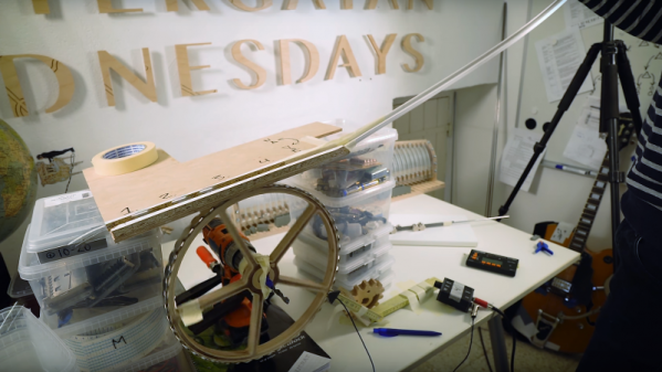
Take a couple of thousand steel balls, add a large wooden gear with neodymium magnets embedded in it, and what do you get? Either the beginnings of a wonderful kinetic music machine, or a mess of balls all stuck together and clogging up the works.

The latter was the case for [Martin], and he needed to find a way to demagnetize steel balls in a continuous process if his “Marble Machine X” were to see the light of day. You may recall [Martin] as a member of the band Wintergatan and the inventor of the original Marble Machine, a remarkable one-man band that makes music by dropping steel balls on various instruments. As fabulous a contraption as the original Marble Machine was, it was strictly a studio instrument, too fragile for touring.

Marble Machine X is a complete reimagining of the original, intended to be robust enough to go on a world tour. [Martin] completely redesigned the lift mechanism, using magnets to grip the balls from the return bin and feed them up to a complicated divider. But during the lift, the balls became magnetized enough to stick together and no longer roll into the divider. The video below shows [Martin]’s solution: a degausser using magnets of alternating polarity spinning slowly under the sticky marbles. As a side note, it’s interesting and entertaining to watch a musician procrastinate while debugging a mechanical problem.

We can’t wait to see Marble Machine X in action, but until it’s done we’ll just settle for [Martin]’s other musical hacks, like his paper-tape programmed music box or this mashup of a synthesizer and a violin.

Continue reading “Keeping Magnetized Marbles From Stopping The Music”

Flying The Friendly Skies With A Hall Effect Joystick

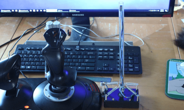
There are plenty of PC joysticks out there, but that didn’t stop [dizekat] from building his own. Most joysticks measure position mechanically using potentiometers or encoders. Only a few high-end models use Hall effect sensors. That’s the route [dizekat] took.

Hall effect sensors are non-contact devices which measure magnetic fields. They can be used to measure the position and orientation of a magnet. That’s exactly how [dizekat] is using a trio of sensors in his design. The core of the joystick is a universal joint from an old R/C car. The center section of the joint (called a spider) has two one millimeter thick disc magnets glued to it. The Hall sensors themselves are mounted in the universal itself. [Dizekat] used a small piece of a chopstick to hold the sensors in position while he found the zero point and glued them in. A third Hall effect sensor is used to measure a throttle stick positioned on the side of the box.

An Arduino micro reads the sensors and converts the analog signal to USB.  The Arduino Joystick Library by [Matthew Heironimus] formats the data into something a PC can understand.

While this is definitely a rough work in progress, we’re excited by how much [dizekat] has accomplished with simple hand tools and glue. You don’t need a 3D printer, laser cutter, and a CNC to pull off an awesome hack!

If you think Hall effect sensors are just for joysticks, you’d be wrong – they work as cameras for imaging magnetic fields too!

Electromagnet-Powered Pendulum

We’re always happy to see hackers inspired to try something different by what they see on Hackaday. To [SimpleTronic] has a project that will let you stretch your analog electronics skills in a really fun way. It’s an electromagnet pendulum analog circuit. Whether you’re building it, or just studying the schematics, this is a fun way to brush up on the non-digital side of the craft.

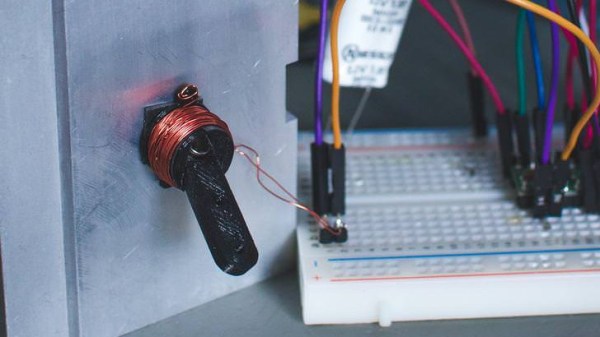
The pendulum is a neodymium magnet on the head of a bolt, dangling on a one foot aluminium chain. Below, a Hall Effect sensor rests atop an electromagnet — 1″ in diameter, with 6/8″ wire coiled around another bolt. As the pendulum’s magnet accelerates towards the electromagnet’s core, the Hall effect sensor registers an increase in voltage. The voltage peaks as the pendulum passes overhead, and as soon as the Hall Effect sensor detects the drop in voltage, the electromagnet flicks on for a moment to propel the pendulum away. This circuit has a very low power consumption, as the electromagnet is only on for about 20ms!

The other major components are a LM358N op-amp, a CD4001B quad CMOS NOR gate, and IRFD-120 MOSFET. [SimpleTronic] even took the time to highlight each part of the schematic in order to work through a complete explanation.

Continue reading “Electromagnet-Powered Pendulum”

Fail Of The Week — Accidental Demagnetization

There’s a trick in the world of plastic enclosures. The threaded insert is a small cylinder of metal with threads on the inside and a rough edge on the outside. To make a plastic part with a hole for securely connecting bolts that can be repeatedly screwed without destroying the plastic, you take the threaded insert and press it (usually with the help of a soldering iron to heat the insert)  into a hole that’s slightly smaller than the insert. The heat melts the plastic a little bit and allows for the insert to go inside. Then when it cools the insert is snugly inside the plastic, and you can attach circuit boards or other plastic parts using a bolt without stripping the screw or the insert. We’ve seen Hackaday’s [Joshua Vasquez] installing threaded inserts with an iron, as well as in a few other projects.

This trick is neat. And I’ve now proven that it does not work with neodymium magnets.

Continue reading “Fail Of The Week — Accidental Demagnetization”

Your Work Won’t Move With A Magnetic Drill Press Vise

Setting up your workpiece is often the hardest part of any machining operation. The goal is to secure the workpiece so it can’t move during machining in such a way that nothing gets in the way of the tooling. Magnetic chucks are a great choice for securely and flexibly holding down workpieces, as this simple shop-built electromagnetic vise shows.

It looks like [Make It Extreme] learned a thing or two about converting microwave oven transformers to electromagnets when they built a material handling crane for the shop. Their magnetic vise, designed for a drill press but probably a great choice for securing work to a milling machine, grinder, or even a CNC router, has a simple but sturdy steel frame. Two separate platforms slide on the bed of the vise, each containing two decapitated MOTs. Wired to mains power separately for selective control and potted in epoxy, the magnets really seem to do the job. The video below shows a very thick piece of steel plate cantilevered out over one magnet while having a hole cut; that’s a lot of down force, but the workpiece doesn’t move.

Like the idea of a shop-made vise but would rather go the old-fashioned way? Check out [Make It Extreme]’s laminated bench vise, which also makes an appearance in this video.

Continue reading “Your Work Won’t Move With A Magnetic Drill Press Vise”