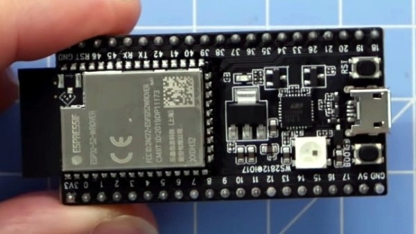
On a typical microcontroller project we may only have access to a relatively tiny screen. Information display can be a challenge, but it’s one that may be made easier by [0xPIT]’s ESParklines library for Espressif processors using the Arduino framework.
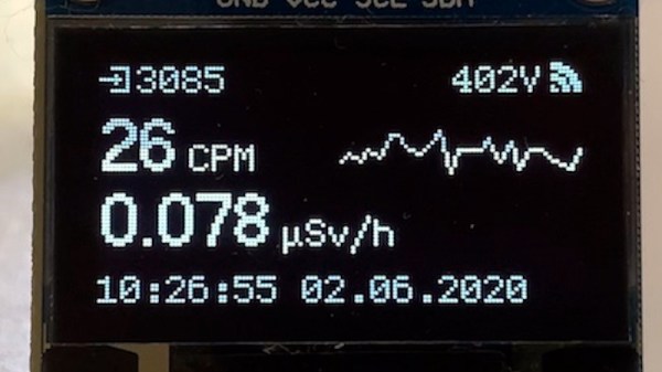
A sparkline is a simple line graph without annotations (like axes or units) intended to fit within the flow of text. They’re largely associated today with the statistician Edward Tufte, and if you’ve not encountered them or Tufte before then we suggest you’ll enjoy educating yourself.
It’s a simple enough library and it comes with example code. Usefully it maintains a data buffer all of its own allowing simple updating, and as well as the examples there is a YouTube video we’ve put below the fold showing graphs evolving as more information is added to them. We’re curious about one thing though, it’s billed as an ESP library, for either the ESP8266 or the ESP32, but we can’t find any ESP-specific code in there and neither could our friendly ESP-guru. Have we missed something? The comments are below if you can shed any light.