Unique LED Display Inspired By Fighter Jet Dashboard

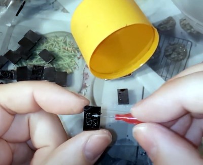
Last year, [Mangy_Dog] was asked by a few friends to consult on a project they were working on. The goal was to build an authentic replica of an F-18 cockpit, apparently for the purposes of creating a film. The project never materialized, but it did inspire him to take a hard look at the 1970s era alphanumeric displays utilized in the real aircraft. One thing lead to another, and he ended up using his own take on the idea to build his own “starburst” digit display.

As [Mangy_Dog] explains, while the faces of these original displays might have been quite small, there was a lot going on behind the scenes. Due to the technical limitations of the time, each alphanumeric character was made up of an array of incandescent light bulbs and fiber optic cables. This worked well enough, but was bulky and complex to manufacture.

Today, we can do better, even on the hobbyist level. As it turns out, 0402 LEDs are just about the right size to recreate the segments of the original starburst displays. So [Mangy_Dog] came up with a simple PCB design to not only align the LEDs properly, but drive them with a 74HC595 shift register and an array of MOSFETs. While assembly wasn’t without its challenges, he made good use of his custom built reflow oven to get all the diminutive components in place.

He went through a few different ideas for the diffuser, but eventually settled on black plastic with tiny holes drilled through courtesy of his laser cutter. Behind each set of three holes is a small pocket that got filled from both sides with transparent UV resin, which was then sanded down after curing. The end result isn’t perfect as you can still tell the center dot is brighter than its peers, but the overall effect is still very nice and definitely has a sort of faux-retro appeal.

The military naturally has access to some incredible technology, though they have a tendency to hold onto it for decades. That an individual with a meager budget and homemade tools can improve upon a piece of hardware installed in a $60+ million airplane is a testament to just how fast things are moving.

Continue reading “Unique LED Display Inspired By Fighter Jet Dashboard”

Cool Off With A Piezo And A Glass Of Water

Some cool-mist humidifiers work by flinging water at a vaporizer, but our favorite kind uses a piezoelectric transducer. These work by using high-frequency sound waves to pound the surface of the water with mechanical energy. That energy introduces standing waves that force the water to break apart into a fine mist on the surface of the piezo disk.

The driving circuit for this DIY mist maker uses a 555 to generate 113 KHz, a trimmer potentiometer to fine-tune it, and a MOSFET to amplify the signal. You don’t need much more than that and a handful of passives to recreate this cool junk box experiment, but the spec of the piezo disk is quite important. The circuit is designed for atomizing transducers, which have a resonant frequency of 113 KHz — much higher than your average junk box piezo. Check out the demo and build video after the break.

Atomizing transducers can do way more than than moisten the air for our comfort. They’re not picky about where the water comes from, so if you have enough of them, you can dry a load of laundry in a few minutes.

Continue reading “Cool Off With A Piezo And A Glass Of Water”

ESP32 Trail Camera Goes The Distance On AA Batteries

There’s no shortage of things to like about the ESP8266 and ESP32, but if we had to make a list of the best features these WiFi-enabled microcontrollers have to offer, their power management capabilities would certainly be near the top. Which is how we assumed [Mark] was able to take a whopping 23,475 pictures on his ESP32 camera while powered by nothing more exotic than four AA batteries from the grocery store.

But as it turns out, the full story is quite a bit more interesting. As far as we can tell, [Mark] isn’t bothering with the ESP32’s sleep modes all. In fact, it looks like you could pull this trick off with whatever chip you wanted, which certainly makes it worth mentally filing away for the future; even if it depends on a fairly specific use case.

In the most simplistic of terms, [Mark] is cutting power to the ESP32 completely when it’s not actively taking pictures. The clever circuit he’s come up with only turns on the microcontroller when a PIR sensor detects something moving around in front of the camera. Once the chip is powered up and running code, it brings one of its GPIO pins high which in turn triggers a 4N37 optoisolator connected to the gate on the circuit’s MOSFET. As long as the pin remains high, the circuit won’t cut power to the ESP32. This gives the chip time to take the requested number of pictures and get everything in order before bringing the pin low and allowing the circuit to pull the plug.

If you’re looking to maximize runtime without wrangling any MOSFETs, we’ve seen some excellent examples of how the low power modes on the ESP8266 and ESP32 can be put to impressive use.

[Thanks to Jason for the tip.]

A Simple Yet Feature-Packed Programmable DC Load

If you’ve got the hankering to own a lab full of high-end gear but your budget is groaning in protest, rolling your own test equipment can be a great option. Not everything the complete shop needs is appropriate for a DIY version, of course, but a programmable DC load like this one is certainly within reach of most hackers.

This build comes to us courtesy of [Scott M. Baker], who does his usual top-notch job of documenting everything. There’s a longish video below that covers everything from design to testing, while the link above is a more succinct version of events. Either way, you’ll get treated to a good description of the design basics, which is essentially an op-amp controlling the gate of a MOSFET in proportion to the voltage across a current sense resistor. The final circuit adds bells and whistles, primarily in the form of triple MOSFETS and a small DAC to control the set-point. The DAC is driven by a Raspberry Pi, which also supports either an LCD or VFD display, an ADC for reading the voltage across the sense resistor, and a web interface for controlling the load remotely. [Scott]’s testing revealed a few problems, like a small discrepancy in the actual amperage reading caused by the offset voltage of the op-amp. The MOSFETs also got a bit toasty under a full load of 100 W; a larger heatsink allows him to push the load to 200 W without releasing the smoke.

We always enjoy [Dr. Baker]’s projects, particularly for the insight they provide on design decisions. Whether you want to upgrade the controller for a 40-year-old game console or giving a voice to an RC2014, you should check out his stuff.

Continue reading “A Simple Yet Feature-Packed Programmable DC Load”

Solid State Relay Simulation, Explained

[SaltyPuglord] needed a solid state relay for a project. We’d have just bought one, but he decided to design his own in LTSpice. Along the way he made the video below, which is pretty informative and a good example of a non-trivial design in LTSpice.

MOSFETs have made designs like this a lot easier, to the extent that it should be as easy as putting a pair of beefy fets in-line with the AC source and load. However, that has a few ramifications that [Salty] covers in the video.

The biggest concern comes in isolating the DC supply from ground. He used a transformer which is tricky to simulate in LTSpice. Beyond that the design of the power supply is quite simple, and as he mentions in the video, you don’t really need this complex of a regulator just to feed the gates of the MOSFETs.

Continue reading “Solid State Relay Simulation, Explained”

Liquid Cooling Keeps This Electronic Load’s MOSFETs From Burning

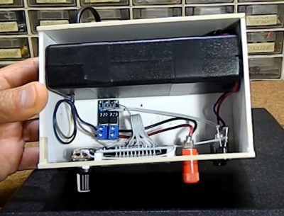
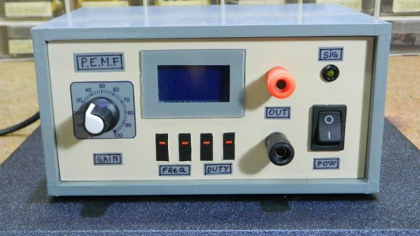
Problem: your electronic load works fine, except for the occasional MOSFET bursting into flames. Solution: do what [tbladykas] did, and build a water-cooled electronic load.

One can quibble that perhaps there are other ways to go about preventing your MOSFETs from burning, including changes to the electrical design. But he decided to take a page from [Kerry Wong]’s design book and go big. [Kerry]’s electronic load was air-cooled and capable of sinking 100 amps; [tbladykas] only needed 60 or 70 amps or so. Since he had an all-in-one liquid CPU cooler on hand, it was only natural to use that for cooling.

The IXYS linear MOSFET dangles off the end of the controller PCB, where the TO-247 device is soldered directly to the copper cold plate of the AiO cooler. This might seem sketchy as the solder could melt if things got out of hand, but then again drilling and tapping the cold plate could lead to leakage of the thermal coupling fluid. It hasn’t had any rigorous testing yet – his guesstimate is 300 Watts dissipation at this point – but as his primary endpoint was to stop the MOSFET fires, the exact details aren’t that important.

We’ve seen a fair number of liquid-cooled Raspberry Pis and Arduinos before, but we can’t find an example of a liquid-cooled electronic load. Perhaps [tbladykas] is onto something with this design.

New Silicon Carbide Semiconductors Bring EV Efficiency Gains

After spending much of the 20th century languishing in development hell, electric cars have finally hit the roads in a big way. Automakers are working feverishly to improve range and recharge times to make vehicles more palatable to consumers.

With a strong base of sales and increased uncertainty about the future of fossil fuels, improvements are happening at a rapid pace. Oftentimes, change is gradual, but every so often, a brand new technology promises to bring a step change in performance. Silicon carbide (SiC) semiconductors are just such a technology, and have already begun to revolutionise the industry.

Mind The Bandgap

A graph showing the relationship between band gap and temperature for various phases of Silicon Carbide.

Traditionally, electric vehicles have relied on silicon power transistors in their construction. Having long been the most popular semiconductor material, new technological advances have opened it up to competition. Different semiconductor materials have varying properties that make them better suited for various applications, with silicon carbide being particularly attractive for high-power applications. It all comes down to the bandgap.

Electrons in a semiconductor can sit in one of two energy bands – the valence band, or the conducting band. To jump from the valence band to the conducting band, the electron needs to reach the energy level of the conducting band, jumping the band gap where no electrons can exist. In silicon, the bandgap is around 1-1.5 electron volts (eV), while in silicon carbide, the band gap of the material is on the order of 2.3-3.3 eV. This higher band gap makes the breakdown voltage of silicon carbide parts far higher, as a far stronger electric field is required to overcome the gap. Many contemporary electric cars operate with 400 V batteries, with Porsche equipping their Taycan with an 800 V system. The naturally high breakdown voltage of silicon carbide makes it highly suited to work in these applications.

Continue reading “New Silicon Carbide Semiconductors Bring EV Efficiency Gains”