Many of us will have experimented with brushless motors, and some of us will have built our own controllers rather than using an off-the-shelf part. Doing so is a good way to understand their operation, and thus to design better brushless motor powered projects. Few of us will have gone as far as [etischer] though, and embarked upon building our own controller for a 300V 90kW traction motor.
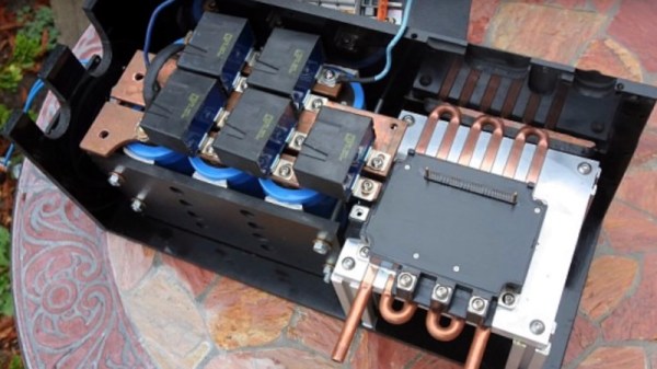
The tricky part of a high power brushless motor controller lies not in the drive but in the high-power switching arrangements. He’s using a bank of IGBTs, and to drive them he’s using a smaller industrial variable frequency drive controller with its own output transistors removed. He takes us through some of the development of the system, including showing him blowing up a set of IGBTs through having too much inductance between transistors and reservoir capacitor, and then to his final design.
This is part of a project VW first converted ten years ago, and as part of a series of videos he’s produced one going through the whole project. It’s a fascinating breakdown of the parts required for an EV conversion, and the teething troubles he’s encountered along the way.