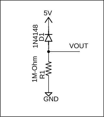
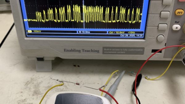
As part of a phosphorescence detector, [lcamtuf] has been working with photodiodes. The components, like all diodes, have some capacitance at the junction, and this can limit performance. That’s why [lcamtuf] turned to bootstrapping to make that parasitic capacitance almost disappear.
The technique appears in several Analog Devices datasheets that presents a mystery. An op amp circuit that would normally limit changes to about 52 kHz has an unusually-placed JFET and claims to boost the bandwidth to 350 kHz.
Why spend a bunch of time and money on such a thing? The obvious answer is “Why not?”, but more specifically, when [lcamtuf]’s son took a shine (lol) to making phosphorescent compounds, it just seemed natural for dad to tag along in his own way. The basic concept of the detector is to build a light-tight test chamber that can be periodically and briefly flooded with UV light, charging up the putatively phosphorescent compounds within. A high-speed photodiode is then used to detect the afterglow, which can be quantified and displayed.
The analog end of the circuit was the far fussier end of the design, with a high-speed transimpedance amplifier to provide the needed current gain. Another scaling amp and a low-pass filter boosts and cleans up the signal for a 14-bit ADC. [lcamtuf] went to great lengths to make the front end as low-noise as possible, including ferrite beads and short leads to prevent picking up RF interference. The digital side has an AVR microcontroller that talks to the ADC and runs an LCD panel, plus switches the 340 nm LEDs on and off rapidly via a low gate capacitance MOSFET.
Unfortunately, not many things found randomly around the average home are all that phosphorescent. We’re not sure what [lcamtuf] tried other than the aforementioned foodstuffs, but we’d have thought something like table salt would do the trick, at least the iodized stuff. But no matter, the lessons learned along the way were worth the trip.
LEDs are a wonderful technology. You put in a little bit of power, and you get out a wonderful amount of light. They’re efficient, cheap, and plentiful. We use them for so much!
What you might not have known is that these humble components have a secret feature, one largely undocumented in the datasheets. You can use an LED as a light source, sure, but did you know you can use one as a sensor?
Experimenting in the world of particle physics probably brings to mind large, expensive pieces of equipment like particle accelerators, or at least exotic elements or isotopes that most of us can’t easily find. But plenty of common objects emit various particles, and it turns out that detecting these particles does not require government backing or acres of test equipment. In fact, you can get this job done with a few readily-available parts and [Tim] shows us how it’s done with his latest project.
The goal of his build is to have a working particle detector for less than $10 per board, although he’s making them in bulk to be used in an educational setting. The board uses a set of photodiodes enclosed in a protective PCB sandwich to detect beta particles from a Potassium-40 source. The high-energy electron interacts with the semiconductor in the photodiode and creates a measurable voltage pulse, which can be detected and recorded by the microcontroller on the board. For this build an RP2040 chip is being used, with a number of layers of amplification between it and the photodetector array used to get signals that the microcontroller can read.
Getting particle physics equipment into the hands of citizen scientists is becoming a lot more common thanks to builds like this which leverage the quirks of semiconductors to do something slightly outside their normal use case, and of course the people building them releasing their projects’ documentation on GitHub. We’ve also seen an interesting muon detector with a price tag of around $100 and an alpha particle detector which uses a copper wire with a high voltage to do its work.
Optoelectronics hold a range of possibilities for the hardware experimenter — indeed who among us hasn’t added LEDs aplenty to our work? What many of us may be unaware of though is that an LED is also a photodiode, and can even be persuaded to generate usable quantities of power. [Voltative] takes a look at this phenomenon with a series of experiments.
Lighting up an LED from a set of other LEDs is pretty cool, as is powering a calculator, or even the calculator powering itself from its on-board LED. But what caught our eye was using two LEDs as a data link, with both of them acting as transmitter and receiver (something on searching we find we’ve seen before). The possibilities there become interesting indeed.
Given that we are now surrounded by LEDs, from OLED screens to LED lighting, we can’t help wondering what the photodiode performance of some other types of part might be. Would the large area of a lighting LED give a better result for example, or would the phosphorescent coating of a white LED make it useless. We feel there’s more scope for experimentation here.
A while back, [Chris Lu] was studying how analog circuits, specifically op-amps can be used to perform mathematical operations and wondered if they could be persuaded to solve differential equations, such as the wave equation. After sitting on the idea for a few years, it was time to make it a reality, and the result is an entry into the Op-Amp Challenge.
Unlike many similar interactive LED matrix displays that are digital in nature (because it’s a lot easier), this design is pure analog, using many, many op-amps. A custom PCB houses a 4×4 array of compute units, each with a blue and white LED indicating the sign and magnitude of the local signal.
The local input signal is provided by an IR photodiode, AC coupled to only respond to change, with every other circuit sharing a sensor to keep it simple. Each circuit is connected to its immediate neighbors on the PCB, and off the PCB via board-to-board connectors. This simple scheme makes this easily scalable if desired in the future.
[Chris] does a great job of breaking down the math involved, which makes this project a neat illustration of how op-amp circuits can implement complex mathematical problems in an easy-to-understand process. Even more op-amps are pressed into service for generating the split-rail voltage reference and for amplifying the weak photodiode signals, but the computation circuit is the star of the show.
Those of use hailing from the UK may be quite familiar with the Royal Air Force’s Tornado fighter jet, which was designed to fight in a theoretical nuclear war, and served the country for over 40 years. This flying deathtrap (words of an actual serving RAF fighter pilot this scribe met a few years ago) was an extremely complex machine, with state-of-the-art tech for its era, but did apparently have a bit of a habit for bursting into flames occasionally when in the air!
Anyway, the last fleet is now long retired and some of the tech inside it is starting to filter down into the public domain, as some parts can be bought on eBay of all places. [Mike] of mikeselectricstuff has been digging around inside the Tornado’s laser head unit, which was part of the bomber’s laser-guided missile subsystem, and boy what a journey of mechanics and electronics this is!
This unit is largely dumb, with all the clever stuff happening deep in an avionics bay, but there is still plenty of older high-end tech on display. Using a xenon-discharge-tube pumped yttrium aluminum garnet (YAG) laser, operating in pulsed mode, the job of the unit is to illuminate the ground target with an IR spot, which the subsequently fired missiles will home on to.
Designed for ground-tracking, whilst the aircraft is operating at speed, the laser head has three degrees of moment, which likely is synchronized with the aircraft movement to keep the beam steady. The optical package is quite interesting, with the xenon tube and YAG rod swimming in a liquid cooling bath, inside a metal housing. The beam is bounced around inside the housing using many prisms, and gated with a Q-switch which allows the beam to build up in intensity, before be unleashed on the target. Also of note is the biggest photodiode we’ve ever seen — easily over an inch in diameter, split into four quadrants, enabling the sensor to resolve direction changes in the reflected IR spot and track its error. A separate photodiode receiver forms part of the time-of-flight optical range finder, which is also important information to have when targeting.
There are plenty of unusual 3-phase positioning motors, position sensors, and rate gyros in the mix, with the whole thing beautifully crafted and wired-up military spec. It is definitely an eye opener for what really was possible during the cold war years, even if such tech never quite filtered down to civilian applications.