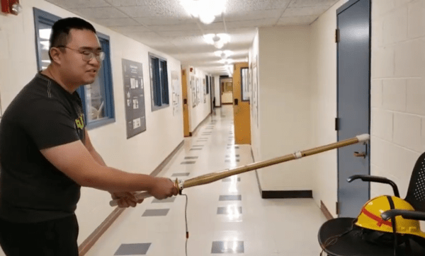
Kendo, a Japanese martial art, is practiced with a special sword. It’s not a particularly sharp sword, though, since the “blade” is essentially a length of bamboo. For this reason, Kendo practitioners must rely on correct form and technique in order to make sure their practice is as effective as possible, and Cornell students [Iman] and [Weichen] have made a Kendo trainer that helps the swordsmen in their art.
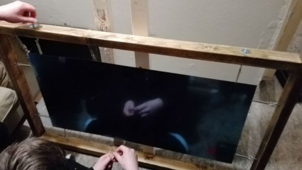
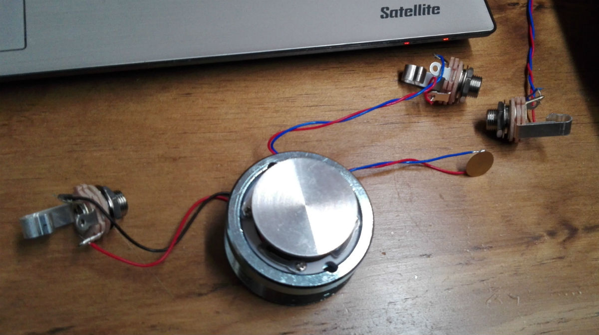
The core of the project is a PIC32 microcontroller hooked up to a set of three piezoelectric sensors and a LSM9DS1 inertial module. The three piezoelectric sensors are attached to a helmet and the inertial module to the sword, and the sensors work together to determine both the location of the strike and whether or not it had enough strength to be considered a “good” strike (the rules of Kendo are beyond the scope of this article). The trainer can then calculate all of the information and provide feedback to the user on a small screen.
While martial-arts related builds seem to be relatively rare, we did find a similar project from back in 2011 called the Virtual Sensei which used a then-popular Kinect in order to track movements. This PIC32-based project, though, seems to be a little more thorough by including the strength of the strike in the information the computer uses, and is probably less expensive to boot!