Homebrew Metrology The CERN Way

We won’t pretend to fully grok everything going on with this open-source 8.5-digit voltmeter that [Marco Reps] built. After all, the design came from the wizards at CERN, the European Organization for Nuclear Research, home to the Large Hadron Collider and other implements of Big Science. But we will admit to finding the level of this build quality absolutely gobsmacking, and totally worth watching the video for.

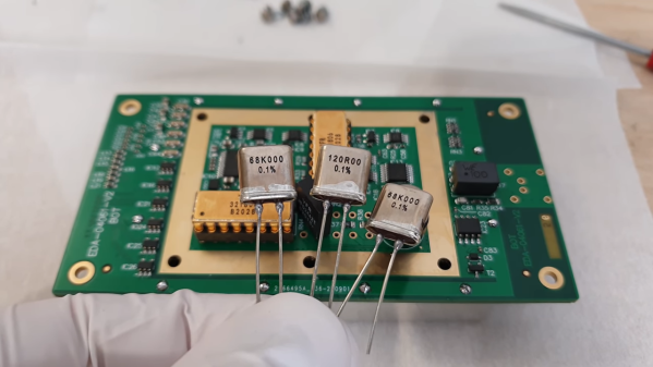
As [Marco] relates, an upcoming experiment at CERN will demand a large number of precision voltmeters, the expense of which led to a homebrew design that was released on the Open Hardware Repository. “Homebrew” perhaps undersells the build a bit, though. The design calls for a consistent thermal environment for the ADC, so there’s a mezzanine level on the board with an intricately designed Peltier thermal control system, including a custom-machined heat spreader blocker. There’s also a fascinatingly complex PCB dedicated solely to provide a solid ground between the analog input connector — itself a work of electromechanical art — and the chassis ground.

The real gem of this whole build, though, is the vapor-phase reflow soldering technique [Marco] used. Rather than a more-typical infrared process, vapor-phase reflow uses a perfluropolyether (PFPE) solution with a well-defined boiling point. PCBs suspended above a bath of heated PFPE get bathed in inert vapors at a specific temperature. [Marco]’s somewhat janky setup worked almost perfectly — just a few tombstones and bridges to fix. It’s a great technique to keep in mind for that special build.

The last [Marco Reps] video we featured was a teardown of a powerful fiber laser. It’s good to see a metrology build like this one, though, and we have a feeling we’ll be going over the details for a long time.

Continue reading “Homebrew Metrology The CERN Way”

Enormous CNC Router Uses Clever Tricks To Improve Performance

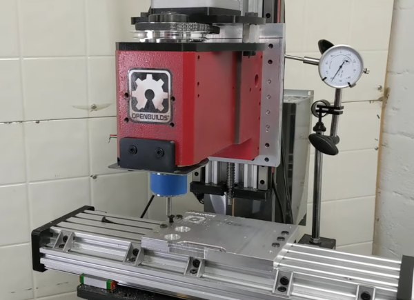
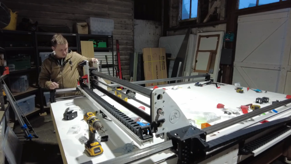
CNC machines made from wood and 3D-printed parts may be popular, but they aren’t always practical from a precision and repeatability standpoint. This is especially true as the machines are scaled up in size, where the compliance of their components starts to really add up. But can those issues be resolved? [jamie clarke] thinks so, and he’s in the process of building a CNC router that can handle a full sheet of plywood. (Video, embedded below.)

This is very much a work in progress, and the videos below are only the very beginning of the process. But we found [jamie]’s build interesting even at this early point because he has included a few clever tricks to control the normal sources of slop that plague larger CNC machines. To provide stiffness on a budget, [jamie] went with a wooden torsion-box design for the bed of his machine. It’s the approach taken by the Root CNC project, which is the inspiration for this build. The bed is formed from shallow boxes that achieve their stiffness through stressed skins applied to rigid, lightweight frames.

Upon the torsion-box bed are guide rails made from commodity lengths of square steel tubing. Stiff these may be over short lengths, but over the three meters needed to access a full sheet of plywood, even steel will bend. [jamie]’s solution is a support that moves along with the carriage, which halves the unsupported length of the beam at all points of travel. He’s using a similar approach to fight whip in the ball screw, with a clever flip-down cradle at the midpoint of the screw.

So far, we’re impressed by the quality of this build. We’re looking forward to seeing where this goes and how well the machine performs, so we’re paying close attention to the playlist for updates. At an estimated build cost of £1,500, this might be just the CNC build you’ve been looking for.

Continue reading “Enormous CNC Router Uses Clever Tricks To Improve Performance”

Precision Optics Hack Chat With Jeroen Vleggaar Of Huygens Optics

Join us on Wednesday, December 2nd at noon Pacific for the Precision Optics Hack Chat with Jeroen Vleggaar!

We sometimes take for granted one of the foundational elements of our technological world: optics. There are high-quality lenses, mirrors, filters, and other precision optical components in just about everything these days, from the smartphones in our pockets to the cameras that loom over us from every streetlight and doorway. And even in those few devices that don’t incorporate any optical components directly, you can bet that the ability to refract, reflect, collimate, or otherwise manipulate light was key to creating the electronics inside it.

The ability to control light with precision is by no means a new development in our technological history, though. People have been creating high-quality optics for centuries, and the methods used to make optics these days would look very familiar to them. Precision optical surfaces can be constructed by almost anyone with simple hand tools and a good amount of time and patience, and those components can then be used to construct instruments that can explore the universe wither on the micro or macro scale.

Jeroen Vleggaar, know better as Huygens Optics on YouTube, will drop by the Hack Chat to talk about the world of precision optics. If you haven’t seen his videos, you’re missing out!

When not conducting optical experiments such as variable surface mirrors and precision spirit levels, or explaining the Double Slit Experiment, Jeroen consults on optical processes and designs. In this Hack Chat, we’ll talk about how precision optical surfaces are manufactured, what you can do to get started grinding your own lenses and mirrors, and learn a little about how these components are measured and used.

join-hack-chatOur Hack Chats are live community events in the Hackaday.io Hack Chat group messaging. This week we’ll be sitting down on Wednesday, December 2 at 12:00 PM Pacific time. If time zones baffle you as much as us, we have a handy time zone converter.

Click that speech bubble to the right, and you’ll be taken directly to the Hack Chat group on Hackaday.io. You don’t have to wait until Wednesday; join whenever you want and you can see what the community is talking about.

Continue reading “Precision Optics Hack Chat With Jeroen Vleggaar Of Huygens Optics”

The B-Sides: Curious Uses Of Off-the-Shelf Parts

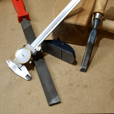
I admit: a few years of prototyping without easy machine shop access really whets my tastebuds for turning metal chips. But all that time spent away from proper machine tools has also pushed me to re-imagine part catalogs, something I see almost every day. Without any precision metalworking tools handy, stock mechanical parts have become my supplement for complexity. And so a former dogma to machine-everything-thyself has been transformed into a hunt for that already-made-part-that-does-it-for-you.

But with part catalogs featuring tens of thousands of purpose-built parts, I started reimagining some of them for other misdeeds. And after a few years spent reinventing use cases for some of these parts, I’m about ready to tell you how to misuse them properly. So today I’d like to show you some of my favorite mechanical part B-sides, so to speak. These are ordinary parts in unorthodox places–something you surely won’t find in the datasheet! Now let’s have a look. Continue reading “The B-Sides: Curious Uses Of Off-the-Shelf Parts”

Finding Perfect Part Fits With The Goldilocks Approach (and OpenSCAD)

There is something to be said for brute force or trial-and-error approaches to problems, especially when finding a solution has an empirical element to it. [Tommy] perceived that to be the case when needing to design and 3D print servo horns that would fit factory servos as closely as possible, and used OpenSCAD to print a “Goldilocks array” from which it was possible to find a perfect match for his printer by making the trial and error process much more efficient. By printing one part, [Tommy] could test-fit dozens of options.

What made doing this necessary is the fact that every 3D printer has some variance in how accurately they will reproduce small features and dimensions. A 6.3 mm diameter hole in a CAD model, for example, will not come out as exactly 6.3 mm in a 3D-printed object. It will be off by some amount, but usually consistently so. Therefore, one way around this is to empirically determine which measurements result in a perfect fit, and use those for production on that specific 3D printer.

That’s exactly what [Tommy] did, using OpenSCAD to generate an array of slightly different sizes and shapes. The array gets printed out, servos are test-fitted to them, and whichever option fits best has its dimensions used for production. This concept can be implemented in any number of ways, and OpenSCAD makes a decent option due to its programmatic nature. Interested in OpenSCAD? It will run on nearly any hardware, and you can get up and running with the basics in probably less than ten minutes.

Screwy Math For Super Fine Adjustments: Differential Screws

For any sort of precision machine, precision adjustability is required. For the hacker this usually involves an adjustment screw, where the accuracy is determined by the thread pitch. This was not good enough for [Mark Rehorst] who wanted adjustment down to 10 μm for his 3D printer’s optical end-stop, so he made himself a differential adjustment screw.

Tiny adjustment can be made to the green block due to the thread pitch differences

Differential screws work by having two threads with a slightly different pitch on the same shaft. A nut on each section of thread is prevented from rotating in relation to the other, and when the screw is turned their relative position will change only as much as the difference between the two thread pitches.

The differential screw in this case started life as a normal M5 bolt with a 0.8 mm thread pitch. [Mark] machined and threaded section of the bolt down to a M4 x 0.7 mm thread. This means he can get 0.1 mm (100 μm) of adjustment per full rotation. By turning the bolt 1/10 rotation, the  relative movement comes down to 10 μm.

This mechanism is not new, originating from at least 1817. If you need fine adjustments on a budget, it’s a very elegant way to achieve it and you don’t even need a lathe to make your own. You can partially drill and tap a coupling nut, or make a 3D printed adapter to connect two bolts.

Fabricating precision tools on a budget is challenging but not impossible. We’ve seen some interesting graphite air bearings, as well as a 3D printed microscope with a precision adjustable stage.

[Ben Krasnow]’s Take On DIY Air Bearings

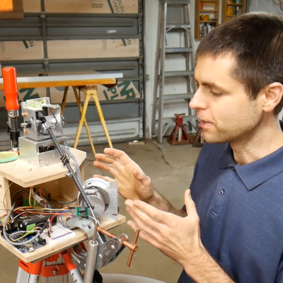
We’ve got to admit that watching [Ben Krasnow]’s new video on air bearings is tough. We found our eyes constantly checking the spherical air bearing in the foreground, which for the first eight minutes of the video just kept going. It was strangely hypnotic, and made it hard to concentrate on all the other cool stuff [Ben] was up to.

If the topic of air bearings seems familiar, it might be because we recently reported on DIY air bearings made from used EDM electrodes. [Ben] saw that too, and dusted off his old air bearing project. Literally, as it turns out, because the graphite blocks whose porosity and softness make them the perfect material for air bearings also makes for a dusty workshop. We’d recommend breathing protection of some sort while machining graphite. In addition to simple puck bearings, [Ben] came up with more complicated designs, including the aforementioned spherical bearing. He used the steel ball itself as a precision tool to grind the graphite out, first by coating it with abrasive and then by cutting grooves in it to act like a file. A cylindrical bearing was also cut, this time with sandpaper glued directly to the ground steel rod that would seat in the bearing.

[Ben]’s other innovation is vacuum preloading, where he applies both vacuum and pressure to the bearing plenum. The vacuum provides the force needed to capture the moving element while the pressure bears the load. It’s a careful balancing act, but it works well enough to capture the large steel ball and keep it turning effortlessly.

We really liked [Ben]’s take on air bearings, especially his thoughts on creating fully enclosed cylindrical bearings. Those could be useful for low-friction linear drives, and we look forward to seeing more on those.

Continue reading “[Ben Krasnow]’s Take On DIY Air Bearings”