If there’s one this we electronics engineers are precious about, it’s our test gear. The instruments themselves can be obscenely expensive, since all that R&D effort needs to be paid back over a much smaller user base compared to say a DVD player. The test probes themselves can often come with an eye-watering price tag as well. Take the oscilloscope probe, pretty much everyone who tinkers with hardware will be familiar with. It’s great for poking around, looking desperately for inspiration when you’re getting stuck in with some debug, but you’ve only got two hands, and that doesn’t leave any spare for button pushing.
Hands-free probing solutions exist, but they can be pricey, flimsy or just a pain to use. Sometimes you just want to solder a wire and leave the probe attached, hoping the grounding lead doesn’t fall off and short something. We’ve seen many solutions to this, so here’s yet another one you can 3D print yourself, so it’s almost free to make.
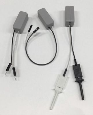
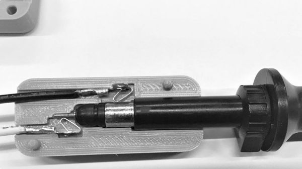
The two-part 3D printed assembly embeds a pair of wires with a Molex 0008500113 sprung terminal on one end, which can be terminated with your choice of pins, headers or just a pair of plain ‘ol wires. Once you’ve dropped your wiring of choice inside, simply glue the halves with a little cyanoacrylate and you’re good to go. Designed around the Siglent 200MHz PP215 specifically, it is likely compatible with many other brands. Thingiverse only has STL files (sigh!) so it may be tricky to adapt it to your exact probe dimensions, but the idea is good at least.
There is no shortage of electronics probing solutions out there, and boy have we covered a few over the years, here’s a low-cost current probe, an Open Source 2 GHz scope probe, and if you want to get really hacky, look no further for inspiration than the 2019 Hackaday SuperCon SMD Challenge.
Thanks [daniel] for the tip!