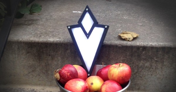
I’m working on a Skyrim quest marker. You probably know what this is even if you never have played the game. When a character or location in the game relates to a quest, an arrow floats over it so you don’t miss it. If it’s a book, the book has the arrow floating over it. If it’s a person, it floats over that character’s head. It is that quest marker I aim to re-create.
I sat down in front of my sketchbook and drew the basic parameters. I wanted it to be approximately to scale to the human/elf/orc heads it usually floats above. I ended up going with around 9 inches from top to bottom. In terms of thickness, any amount of blatant dimensionality is bad, as the game element exists in only 2 dimensions. That said, I will be re-creating this thing in the real world, and LEDs and acrylic and plywood and other things need to go inside.
I decided to make it around 1.25 inches thick, which would include enough space for a 9V battery if I so chose, plus a proto board and microcontroller.
Designing the Electronics
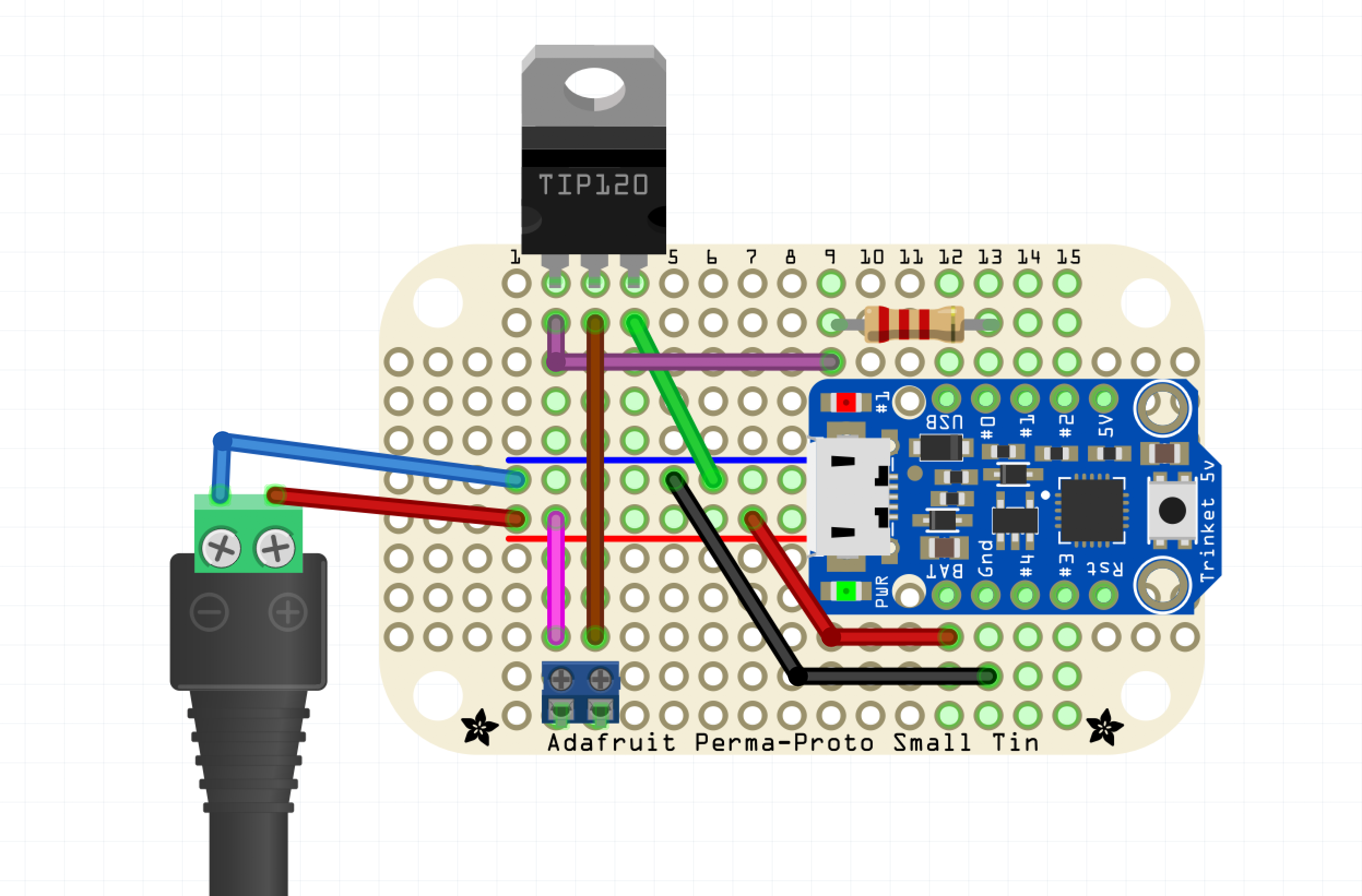 Before I finalized the dimensions I had to design the circuit. Originally I looked at Adafruit’s backlight LED panels, but I felt it would be too hard to fit into the pointy parts of the enclosure, both physically and in terms of light distribution. Instead I went with a strand of cold white LEDs, not individually addressable but only require power and GND to light up. However, the strand is WAY too bright straight from the battery. Fortunately, the strand is PWMable so I am using an Adafruit Trinket ATtiny85 breakout to dim it down somewhat.
I chose a TIP-120 for the switching, a part highly recommended by our own [Adam Fabio]. Power supply will be my wall wart; if I were to take it out into the wild, I could put a 9V battery inside the enclosure — there’s room — but I think I’ll just have it at home this time around.
Designing the Enclosure
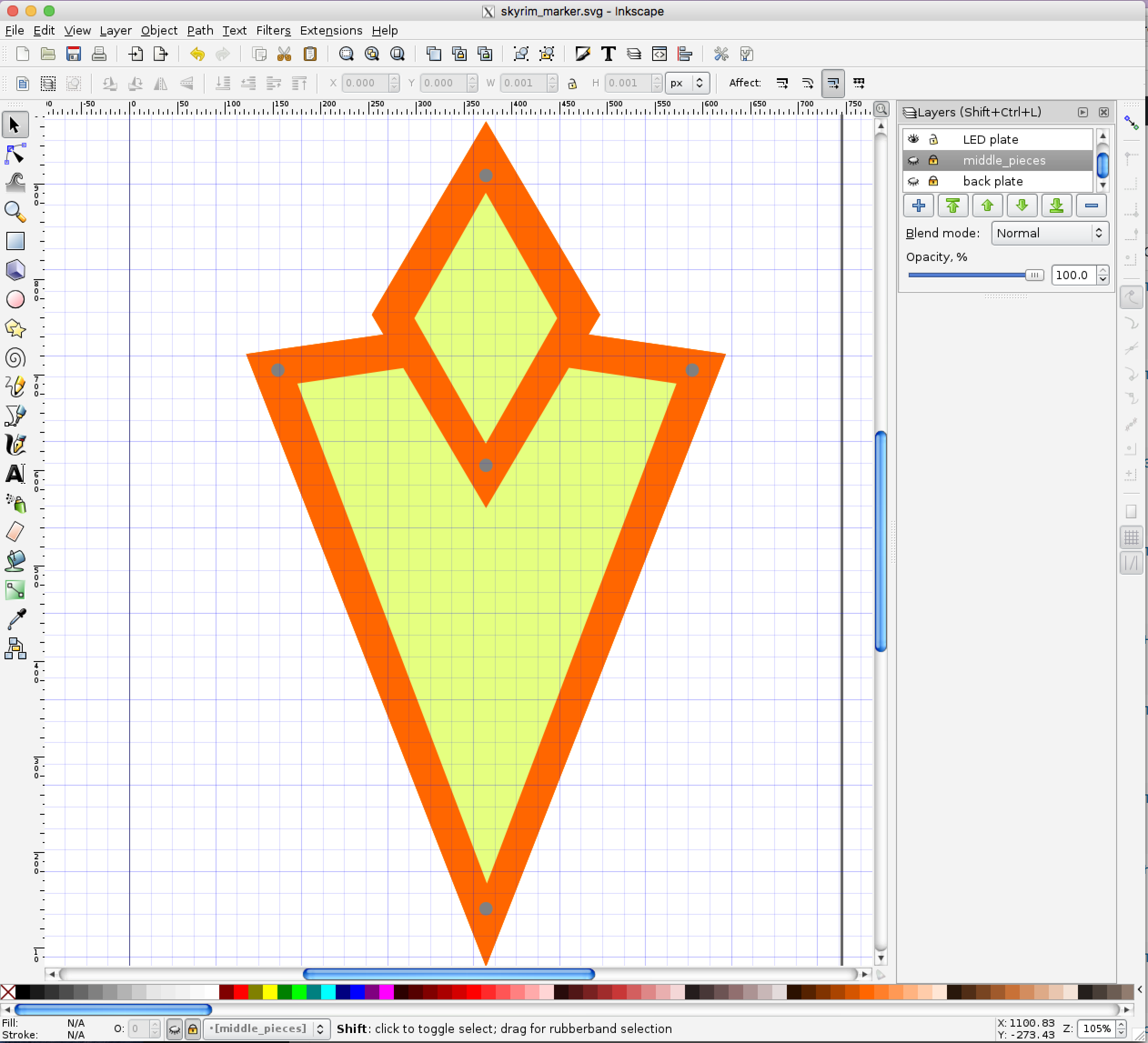 I decided to be flexible with my design. I was going use the laser cutter to cut each layer of the marker out of eighth-inch material. The front will have a bezel holding the acrylic in place, while the back is just a blank piece of plywood. The interior layers, of unknown quantity (as I designed it) would determine the overall thickness of the marker.
I opened up Inkscape and went to work designing the layers. I did everything in a single Inkscape file with each layer corresponding with a similar layer on the design.
Closer to lasering, when I have a good sense of the projects’s final parameters, I’ll distribute the layers on a series of 12”x12” Inkscape canvases, and I’ll print directly from these. This will allow me to cut some filler projects in the unused portion of the boards, because I’m cheap like that.
The topmost bezel was easy — it’s supposed to look a specific way. I dropped a GIF from the ‘nets into Inkscape and traced it. I duplicated that layer and made the bottom plate, which is basically just a filled-in version of the bezel. There needed to be the vinyl for the light-emitting part, with some sort of bezel keeping it in place. There also needed to be a board for the LEDs, and beneath the LED board there needed to be room for a small circuit board.
I ended up making the whole thing 10 layers thick: Beginning from the top: the outer bezel; then the acrylic and its carrier, which nestle together — I didn’t want any light escaping from the sides. The third layer is an “under bezel” which lifts the acrylic up 1/8” because the LED strips are covered in a little “hill” of plastic. Fourth, the LED plate, painted white with lengths of LED strip attached to it.
I consider those four layers to be the top of the project. The next six are the bottom, consisting of five identical layers making up the electronics compartment, with the back plate, which also has a hole for the power supply and also mounts the protoboard. Each layer is 1/8″ thick, for an overall thickness of 1.25″ — not too bad. It’s somewhat on the heavy side. (By the way, you can find the Inkscape file in the project page.)
Lasering
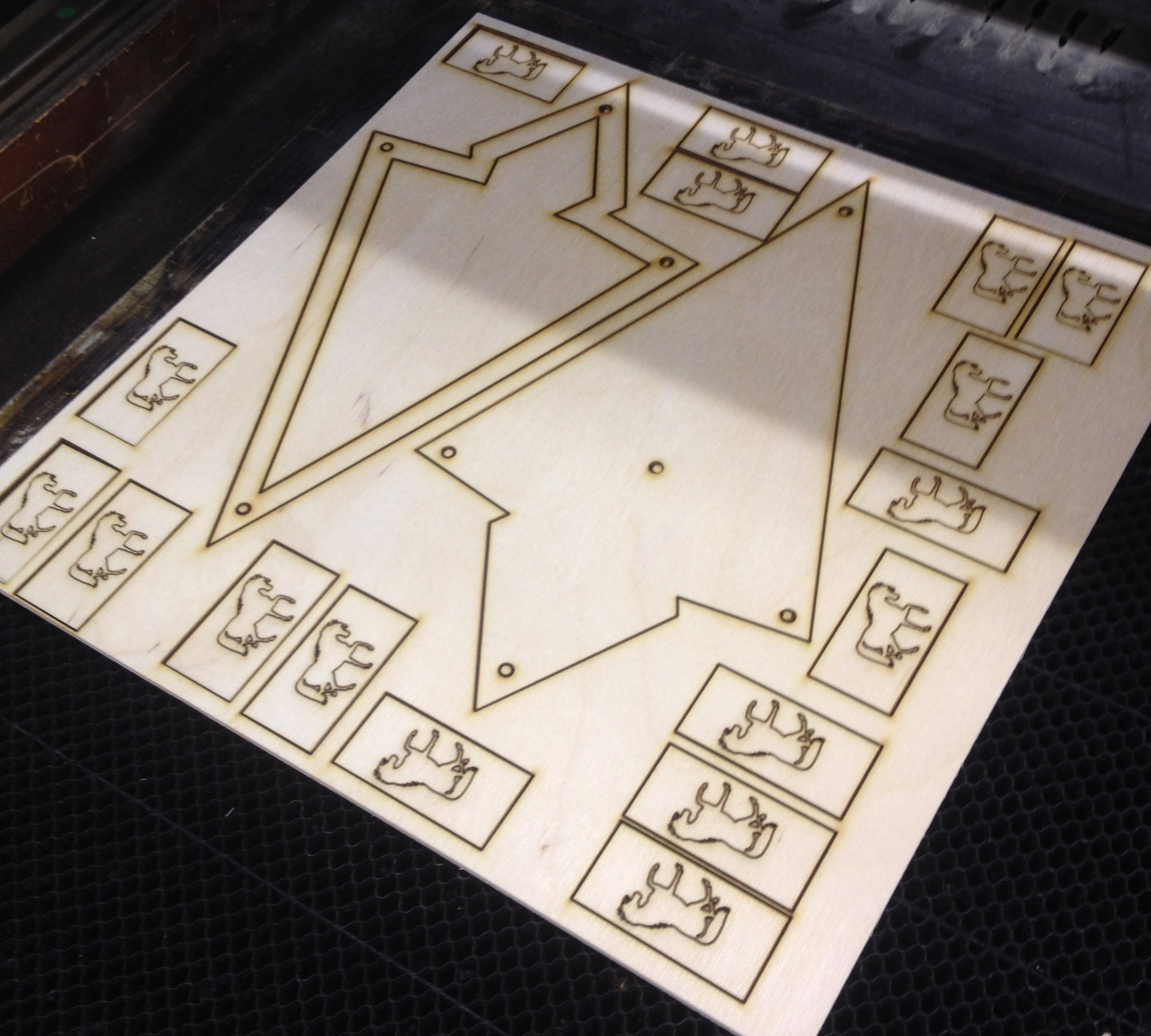 The first fifteen minutes of lasering was hell, as I got all the settings figured out. But once I got everything dialed in, it was a breeze.
The layers were split onto 12″x12″ sheets, with two layers per. So I imported 1″x2″ rectangles with horse shapes on them, and you can see them on the right. We use these in my gaming group for horses, with a figure sitting on top of it to show he or she is mounted.
Once I got dialed into my favorite settings, the lasering went quite well. The wood was about one notch lower in terms of quality than what I’m used to, and I felt like the glue was just a little more refractory or whatever. Still, most of the parts came out perfectly.
I was mostly worried about the acrylic. I took a chance with some translucent white acrylic I found on Amazon. Having never used it before, or had a clear understanding (sorry) of how translucent it was, I bought it sight unseen. Furthermore, I had enough real estate on my 12″x12″ sheet for maybe 3 cuts, so I wanted to get the right settings ASAP.
It worked better than I could have hoped. Someone at the hackerspace had written the best ratio of speed and power on the laser cutter room’s whiteboard walls — 15 speed, 8 power. I ran it through twice to be sure, but it came out perfect, and slid into place like a charm.
The Build
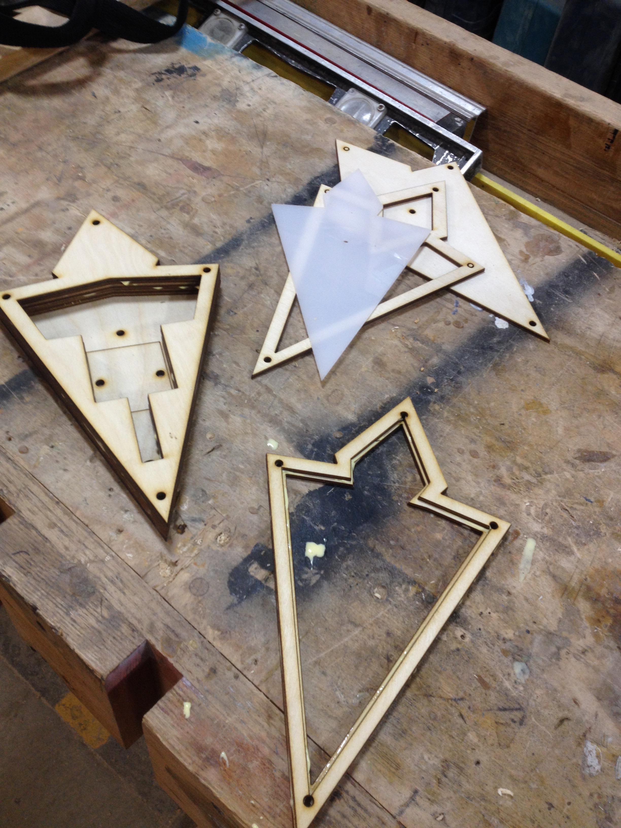 I glued the bottom six layers right there in the hackerspace, as well as the two-layer carrier for the acrylic. All I needed to do was paint the thing, add the electronics, and bolt it together.
Originally I’d envisioned a battery pack inside a harness of some sort, with a black-painted PVC pipe hoisting the marker overhead. That seems like a lot to tackle between now during my first run at the project, so I converted the idea to a tabletop version that uses a wall wart.
When I was prototyping the electronics it had occurred to me that I might be a little ridiculous about the Trinket — what if it didn’t need to be PWMed down? Oh, but it does. LED strips run at full brightness are awfully bright, and that cold white that has all the subtlety of a klieg light. They definitely need to be PWMed down.
The strip comes with a 3M adhesive backing, which was great, However, the solder pads that were most accessible were on the underside, as the top is covered in a plastic bubble that is hard to cut away, even with a sharp knife.
For the future development, I plan to swap in an ESP and use it as a Twitter alert. In addition, the enclosure was hastily designed and lacked a certain polish. For instance, I would like to use trapped nuts on the top three layers to secure the front bezel from behind, so it doesn’t have those intrusive socket heads showing — or at least inset them somehow.
But all in all I’m happy to have the enclosure work out so well the first try. After countless lasered projects with every grade of success from “abject debacle” on up, maybe I’m starting to get a hang of it! Check out the project page on Hackaday.io.