Action cameras like the GoPro, and the Sony Action Cam are invaluable tools for cyclists and anyone else venturing into the great outdoors. These cameras are not really modifiable or usable in any way except for what they were designed for. [Connor] wanted a cheaper, open-source action camera and decided to build one with the Raspberry Pi.
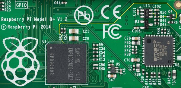
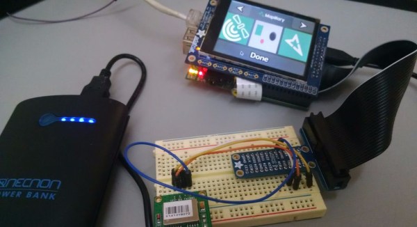
[Connor]’s Pi action cam is built around the Raspberry Pi Model A+ and the Pi camera. This isn’t a complete solution, so [Connor] added a bluetooth module, a 2000 mAh battery, and a LiPo charger.
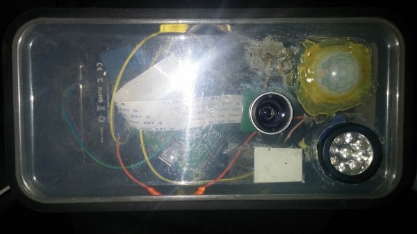
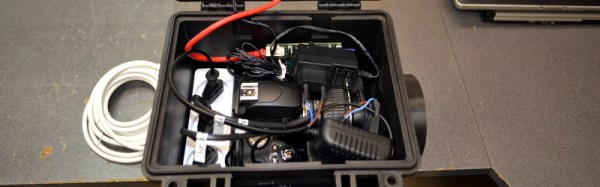
To keep the Pi Action Cam out of the elements, [Connor] printed an enclosure. It took a few tries, but eventually he was able to mount everything inside a small plastic box with buttons to start and stop recording, a power switch, and a USB micro jack for charging the battery. The software is a script by [Alex Eames], and the few changes necessary to make this script work with the hardware are also documented.
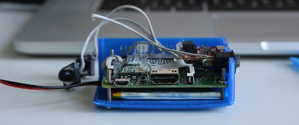
This was the most intensive 3D printing project [Connor] has ever come up with, and judging by the number of prints that don’t work quite right, he put a lot of work into it. Right now, the Pi action cam works, but there’s still a lot of work to turn this little plastic box into a completed project.
 Once the Pi was outfitted with a 3G modem, [madis] can log in and change the camera settings from anywhere. It’s normally set up to take a picture once every fifteen minutes, but ONLY during working hours. Presumably this saves a bunch of video editing later whereas a normal timelapse camera would require cutting out a bunch of nights and weekends.